
SLIDE 1
1 ¡
CS240 Computer Organization Department of Computer Science Wellesley College
Latches and Flip-flops
Fundamental elements of memory
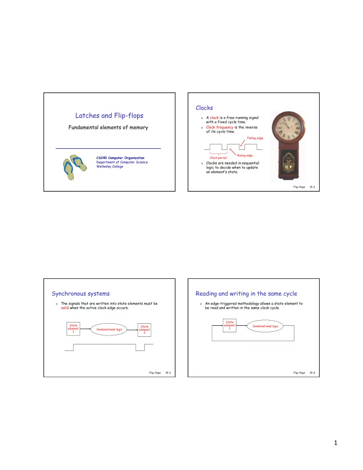
Clocks
- A clock is a free-running signal
with a fixed cycle time.
- Clock frequency is the inverse
- f its cycle time.
- Clocks are needed in sequential
logic to decide when to update an element’s state.
Clock period Falling edge Rising edge
Flip-flops 15-2
Synchronous systems
- The signals that are written into state elements must be
valid when the active clock edge occurs.
State element 1 State element 2 Combinational logic
Flip-flops 15-3
Reading and writing in the same cycle
- An edge-triggered methodology allows a state element to
be read and written in the same clock cycle.
State element 1 Combinational logic
15-4 Flip-flops