
VHDL - Flaxer Eli Ch 8 - 1
Structural Modeling
Chapter 8 Structural Modeling
VHDL
VHDL - Flaxer Eli Ch 8 - 2
Structural Modeling
Outline
Basic Example Component Declaration Component Instantiation Resolving Signal Value Generate Statement
VHDL - Flaxer Eli Ch 8 - 3
Structural Modeling
Structural Modeling
This chapter describes the structural style of modeling. An entity is
modeled as a set of components connected by signals, that is, as a netlist.
The behavior of the entity is not explicitly apparent from its model. The
component instantiation statement is the primary mechanism used for describing such a model of an entity.
COMPONENT & PORT MAP statements are used to implement
structural modeling.
The component instantiation statements are concurrent statements, and
their order of appearance in the architecture body is therefore not important.
A component can, in general, be instantiated any number of times. Each instantiation must have a unique component label.
VHDL - Flaxer Eli Ch 8 - 4
Structural Modeling
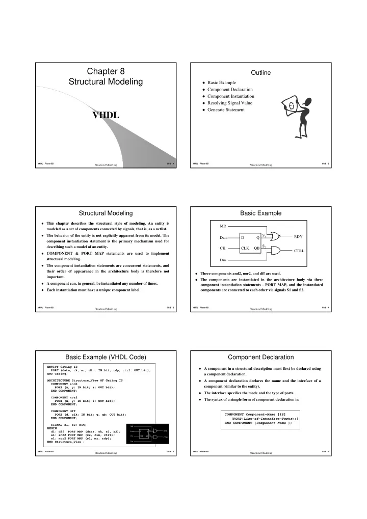
Basic Example
Three components and2, nor2, and dff are used. The components are instantiated in the architecture body via three
component instantiation statements - PORT MAP, and the instantiated components are connected to each other via signals S1 and S2. D CLK Q QB Data CK MR Din RDY CTRL S2 S1
VHDL - Flaxer Eli Ch 8 - 5
Structural Modeling
Basic Example (VHDL Code)
ENTITY Gating IS PORT (data, ck, mr, din: IN bit; rdy, ctrl: OUT bit); END Gating; ARCHITECTURE Structure_View OF Gating IS COMPONENT and2 PORT (x, y: IN bit; z: OUT bit); END COMPONENT; COMPONENT nor2 PORT (x, y: IN bit; z: OUT bit); END COMPONENT; COMPONENT dff PORT (d, clk: IN bit; q, qb: OUT bit); END COMPONENT; SIGNAL s1, s2: bit; BEGIN d1: dff PORT MAP (data, ck, s1, s2); a1: and2 PORT MAP (s2, din, ctrl); n1: nor2 PORT MAP (s1, mr, rdy); END Structure_View ;
D CLK Q QB Data CK MR Din RDY CTRL S2 S1 VHDL - Flaxer Eli Ch 8 - 6
Structural Modeling
Component Declaration
A component in a structural description must first be declared using
a component declaration.
A component declaration declares the name and the interface of a
component (similar to the entity).
The interface specifies the mode and the type of ports. The syntax of a simple form of component declaration is:
COMPONENT Component-Name [IS] [PORT(List-of-Interface-Ports);] END COMPONENT [Component-Name ];