
SLIDE 1
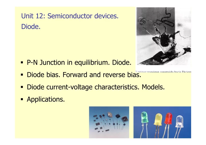
Unit 12: Semiconductor devices. Diode.
- P-N Junction in equilibrium. Diode.
- Diode bias. Forward and reverse bias.
- Diode current-voltage characteristics. Models.
- Applications.