
SLIDE 1
1
- Prof. S. Ben-Yaakov , DC-DC Converters
[5- 1]
Power elements
5.1 Conduction loss calculations 5.2 Diode 5.2.1 Types of diodes 5.2.2 Diode conduction losses 5.2.3 Diode recovery 5.3 Power switches 5.3.1 BJT 5.3.2 MOSFETs 5.3.3 IGBT 5.3.4 Other switches 5.4.4 Switching losses 5.4 Capacitor 5.4.1 Capacitor types 5.4.2 Specifications, model, ESR 5.4.3 Assignments (∆VESR) 5.4.4 Capacitor losses
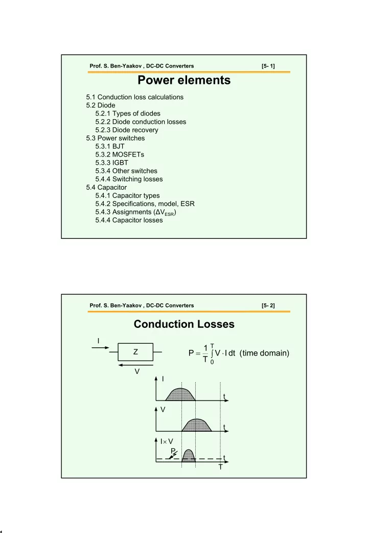
- Prof. S. Ben-Yaakov , DC-DC Converters
[5- 2]
Conduction Losses
) domain time ( dt I V T 1 P
T