
SLIDE 1
1
Photographic Tone Reproduction
Tone Reproduction
Definition: Compressing the dynamic range of a scene’s luminances/radiances so that it can be displayed on a given device in such a way that minimizes the perceptual difference between viewing the scene and viewing the rendering of the scene.
Photographic Response
An alternative to modeling visual response
directly.
Instead, models response to photographic
materials (film/paper).
Photographic Response
Why bother with photographic model?
Far better understood than human visual
system.
Optimized for human viewing Artistic photography Composition of CG elements with scenes
captured on film.
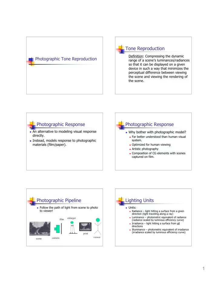
Photographic Pipeline
Follow the path of light from scene to photo
to viewer!
scene camera film enlarger print viewer
Lighting Units
Units:
Radiance – light hitting a surface from a given
direction (light traveling along a ray)
Luminance – photometric equivalent of radiance
(radiance scaled by luminous efficiency curve)
Irradiance – light hitting a surface from all
directions
Illuminance – photometric equivalent of irradiance