
SLIDE 1
Applying Software Product Line Engineering Techniques to Develop Simulators for Early System Integration
Istvan Nagy Loek Cleophas
ASML TU/e
ASML Veldhoven 2011/09/29
PublicThe Team
- Loek Cleophas
TU/e – Software Ernest Mithun Engineering Technology
- Berrie van den Eijnden
ASML – Software Integration
- Istvan Nagy
ASML – Architecture & Platform
- Liviu Raulea
ASML – Embedded Software Dennis Verhaegh
Slide 2 | Public Slide 3 |Introduction
- One of the world’s leading manufacturers of chip-making
equipment
- Makes the scanners that print the chips
- 7697 employees (expressed in FTE, Q2 2011)
- Net sales in million EUR
1,529 (Q2 2011)
- R&D investment in million EUR
145 (Q2 2011)
- Number of systems shipped
63 (Q2 2011)
ASML
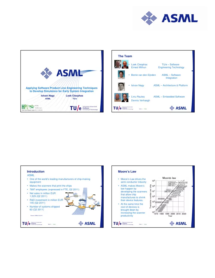
Source: ASML Q2 2011 PublicMoore’s Law
- Moore’s Law drives the
semi conductor industry
- ASML makes Moore’s
law happen by developing the scanners that allow chip manufactures to shrink their device features.
- At the same time the
cost of devices is brought down by increasing the scanner productivity
Slide 4 |