The Muon g-2 Experiment Jenny Holzbauer September 27, 2017 - - PowerPoint PPT Presentation

the muon g 2 experiment
SMART_READER_LITE
LIVE PREVIEW

The Muon g-2 Experiment Jenny Holzbauer September 27, 2017 - - PowerPoint PPT Presentation

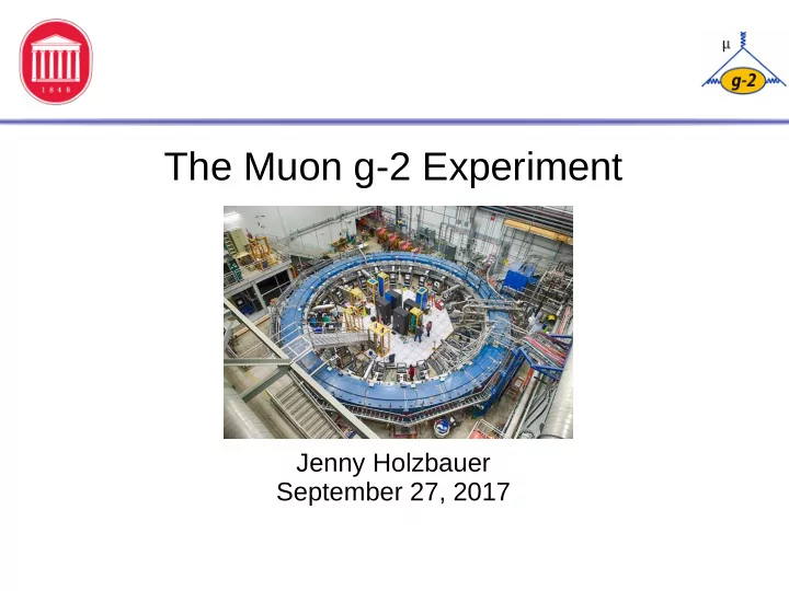
The Muon g-2 Experiment Jenny Holzbauer September 27, 2017 Overview Motivation and some history Comment on theory and its inputs Moving from BNL to Fermilab The planned measurement Experiment setup Measurement strategy


slide-1
SLIDE 1

The Muon g-2 Experiment

Jenny Holzbauer September 27, 2017

slide-2
SLIDE 2

Jenny Holzbauer

2

Overview

  • Motivation and some history
  • Comment on theory and its inputs
  • Moving from BNL to Fermilab
  • The planned measurement
  • Experiment setup
  • Measurement strategy
  • Field and ring installation
  • Experiment status
  • Short review of analysis work for
  • ther experiments
slide-3
SLIDE 3

Jenny Holzbauer

3

Why Muon g-2?

  • g relates spin and magnetic moment
  • Exactly 2 in Dirac theory
  • Higher order effects create contributions

leading to values > 2

  • New physics could cause further deviations
  • f this value
  • Study the anomalous part, aµ=(g-2)/2
  • Muons used because mass is higher than

electrons, giving ~43,000 increased sensitivity (and live much longer than taus)

slide-4
SLIDE 4

Jenny Holzbauer

4

Theory: Components

B

m m g

Q E D

Z

W e a k

K n o w n w e l l b e y o n d c u r r e n t e x p e r i m e n ta l p r e c i s i o n

  • Theorists calculating various terms that

make g > 2, and uncertainties are comparable with experimental

  • Improved calculations, methods and

data inputs to these terms are very important to reduce the uncertainty

  • QED and weak terms are well known,

but hadronic terms are less understood

  • Hadronic vacuum polarization is studied

with e+e- to hadrons data from various experiments and hadronic light by light is estimated with calculations, lattice and indirect data constraints

l b l a c k b o a r d

H a d L b L

p

H a d V P

p

p

H a d V P

p

K n o w n s l i g h tl y b e tte r th a n c u r r e n t e x p e r i m e n ta l p r e c i s i o n – n e e d s w o r k

slide-5
SLIDE 5

Jenny Holzbauer

5

E821 (BNL) Results

Va l u e (x 1 0 -1 1 ) Q ED 1 1 6 5 8 4 7 18 .9 51 ± 0 .00 9 ± 0 .0 19 ± 0 .00 7 ± 0.077 H V P (l o ) 6 9 4 9 ± 4 2 H V P (h o )

  • 9 8 .4 ± 0 .7

H L B L 1 0 5 ± 2 6 EQ 1 5 4 ± 1 To t a l SM 1 1 6 5 9 1 8 02 ± 4 9

a m

E x p t . - a m S M = ( 2 6 0 ± 7 8 ) x 1 0 - 1 1

(3 .3 s )

  • Total SM uncertainty is roughly half the experimental uncertainty

from E821 (BNL version)

  • New E989 will reduce experimental uncertainty by about a

factor of 4 (0.14ppm)

  • If current discrepancy remains at the same level, would give > 5

sigma deviation. Improvements to theory uncertainty could give > 8 sigma deviation.

*Values from TDR, 2015

slide-6
SLIDE 6

Jenny Holzbauer

6

Moving an Experiment

  • After E821, was decided to form a

new experiment E989 at Fermilab

  • 15 ton cryostat ring moved from

Long Island to Chicago by barge and truck- tricky, superconducting coils can't flex >3mm

  • Vacuum chambers and other

components shipped separately

  • Magnet and related cryo-systems

were cooled, powered in 2015

  • 1.45 Tesla field was achieved
  • Transportation was a success!
slide-7
SLIDE 7

Jenny Holzbauer

7

Fermilab Accelerator

  • Reusing anti-proton source

from Tevatron operation, 8 GeV input beam

  • Long decay channel gives low

pion/proton contamination- big improvement!

  • Building new beamline to

transport polarized mu+ beam to g-2 ring

  • Accelerator at Fermilab will

allow 20x more muons, reducing statistical error to 0.1ppm

slide-8
SLIDE 8

Jenny Holzbauer

8

Ring, Detectors and Other Systems

  • Experimental setup consists of
  • Ring and fields (dipole

magnets and electrostatic quadrupole plates) to contain the muons

  • Straw trackers and

calorimeters to detect the electrons which come from muon decays

  • Additional components to

control or measure the beam (inflector, kickers, collimators, monitors), trolley to help measure the field

slide-9
SLIDE 9

Jenny Holzbauer

9

The Measured Quantities

  • We can rewrite this as below:
  • ωp is the proton Larmor frequency measured in a field B
  • ωa is the precession frequency measured with decay positrons
  • µµ/µp magnetic moment ratio from muonium hyperfine

measurement

aµ = ωa/ωp µµ/µp – ωa/ωp

ωc = e m γ B ωS = e m γ B (1 + γ a

µ)

ωS – ωC = ωa = e/m aµ B

slide-10
SLIDE 10

Jenny Holzbauer

10

Measuring spin precession frequency ωa

High energy electron Spin

  • Positrons retain muon spin info
  • 24 calorimeter stations
  • Measure counts, time and

energy

  • Time spectrum of positrons with

E > 1.8 GeV is fit with 5 parameter fit to determine ωa

*Plots from E821, green line shows fit

slide-11
SLIDE 11

Jenny Holzbauer

11

Magic!

  • More formally:
  • With the appropriate choice of p, boxed term will drop out
  • This is the “magic momentum”
  • In real life not all muons are exactly at this momenta (an

uncertainty). Alignment efforts to ensure muon conformity are important.

slide-12
SLIDE 12

Jenny Holzbauer

12

Ring Set-up

  • Inflector in black, kickers in

blue, quads in red

  • Beam comes in through

inflector, which compensates for the 1.45T dipole field

  • Kickers then kick the beam

into a closed orbit

  • Quads offer weak vertical

focusing

  • Other components used to

measure the beam or muons (mostly inside ring)

slide-13
SLIDE 13

Jenny Holzbauer

13

Storage Ring Magnet

  • Storage ring magnet produces

the 1.45 T dipole field

  • Field must be very uniform
  • C-shape required for detectors to

fit inside the ring- also dictates shape of vacuum chambers inside the C

  • Measured with survey trolley

(more range, before vacuum chambers installed), in-vacuum trolley (no beam), and fixed NMR probes on vacuum chambers (with beam, farther away)

slide-14
SLIDE 14

Jenny Holzbauer

14

Storage Ring Alignment: Where the Magic Happens

  • g-2 ring contains cryogenic systems, magnets to generate

dipole B fields, and within those, vacuum chambers

  • Chambers contain quadrupole plates, giving the beam vertical

focusing, and the beam itself is within these plates

  • Alignment of chambers, metal structures (cages) holding the

plates, and the plates themselves, is required to get the beam (ωa), and B field measurement trolley (ωp) in the right spot

  • Critical to reach the magic momenta!
slide-15
SLIDE 15

Jenny Holzbauer

15

Some interesting Variations

  • Most of the quadrapole plates are reused

from BNL. However, near the inflector, the first quad section (Q1) on the outer radius is made from aluminized mylar

  • This is a much thinner plate, which

prevents lost muons in this region, when the beam is still being positioned on the central orbit

  • The kickers are made of two curved

plates, one at the inner and one at the

  • uter radius which have equal and
  • pposite current, divided into three

sections with 10.8 mrad kick to push the muons into the central orbit

slide-16
SLIDE 16

Jenny Holzbauer

16

Initial Field Plots and Goals

  • Similar to BNL- in both cases, improved with metal shims:

Field vs. Azimuth

R-R0(cm) Vertical (cm)

Azimuthally Averaged Field vs r, z

  • October 2015: +/-700 ppm
  • Goal: +/- 25 ppm
  • October 2015: +/-25 ppm
  • Goal: < 1 ppm
slide-17
SLIDE 17

Jenny Holzbauer

17

B Field Measurements from 2016 and 2017

2017

slide-18
SLIDE 18

Jenny Holzbauer

18

Engineering Run: Summer 2017

  • This summer, an engineering run

took place to test the system components

  • May 23 we had first particles

delivered to ring and beam splash

  • bserved in calorimeters
  • Ran through July 7
  • Achieved particles circulating

through the full storage ring and demonstrated the operation of the various systems!

  • New run should start in November,

physics data taking in winter

Calorimeter energy

peaks = lost muons and protons

Reconstructed track through tracker

slide-19
SLIDE 19

Jenny Holzbauer

19

Beam Information from Fiber Harp

The plot shows the cyclotron revolution frequency for the proton on the right and the horizontal betatron oscillation of the proton on the left. The BO frequency arises from the beating of the cyclotron revolution frequency and the CBO frequency (that lives around 300 kHz).

slide-20
SLIDE 20

Jenny Holzbauer

20

Analysis Demonstration

This figure was accumulated from two weeks of data accumulated in June 2017 and has approximately 700k positrons. The number of wiggles is somewhere between that achieved by CERN-II and CERN-III.

slide-21
SLIDE 21

Jenny Holzbauer

21

Summary and Plans

  • Upcoming experiment will improve

uncertainty by a factor of four versus the previous experiment's result

  • Active collaboration with much work
  • ngoing to ensure the operations of

various sub-systems and data analysis

  • Experiment installation and initial

engineering run are completed

  • Expect physics data this winter!

Installation work over the past year or so

slide-22
SLIDE 22

Jenny Holzbauer

22

Other Material

slide-23
SLIDE 23

Jenny Holzbauer

23

Magnet Up-time

slide-24
SLIDE 24

Jenny Holzbauer

24

New Physics Example

slide-25
SLIDE 25

Jenny Holzbauer

25

Measuring the Field (Pictures)