Texture Mapping The Rendering Pipeline CPSC 414 10/24/03 Abhijeet - - PDF document

texture mapping the rendering pipeline
SMART_READER_LITE
LIVE PREVIEW

Texture Mapping The Rendering Pipeline CPSC 414 10/24/03 Abhijeet - - PDF document

Texture Mapping The Rendering Pipeline CPSC 414 10/24/03 Abhijeet Ghosh Texture Mapping Texture Pipeline Associate 2D information with 3D surface Point on surface corresponds to a point in the texture Compute Use projector Use


slide-1
SLIDE 1

Texture Mapping

CPSC 414 10/24/03 Abhijeet Ghosh

The Rendering Pipeline Texture Mapping

  • Associate 2D information with 3D surface

– Point on surface corresponds to a point in the texture

  • Introduced to increase realism

– Lighting/shading models not enough

  • Hide geometric simplicity

– map a brick wall texture on a flat polygon – create bumpy effect on surface

Texture Pipeline

Compute

  • bject space

location Use projector function to find (u, v) Use corresponder function to find texels Apply value transform function (e.g., scale, bias) Modify illumination equation value

Texture Pipeline

v u eye Texel color (0.9,0.8,0.7) (x, y, z) Object position (-2.3, 7.1, 17.7) (u, v) Parameter space (0.32, 0.29) Texture Image space (81, 74)
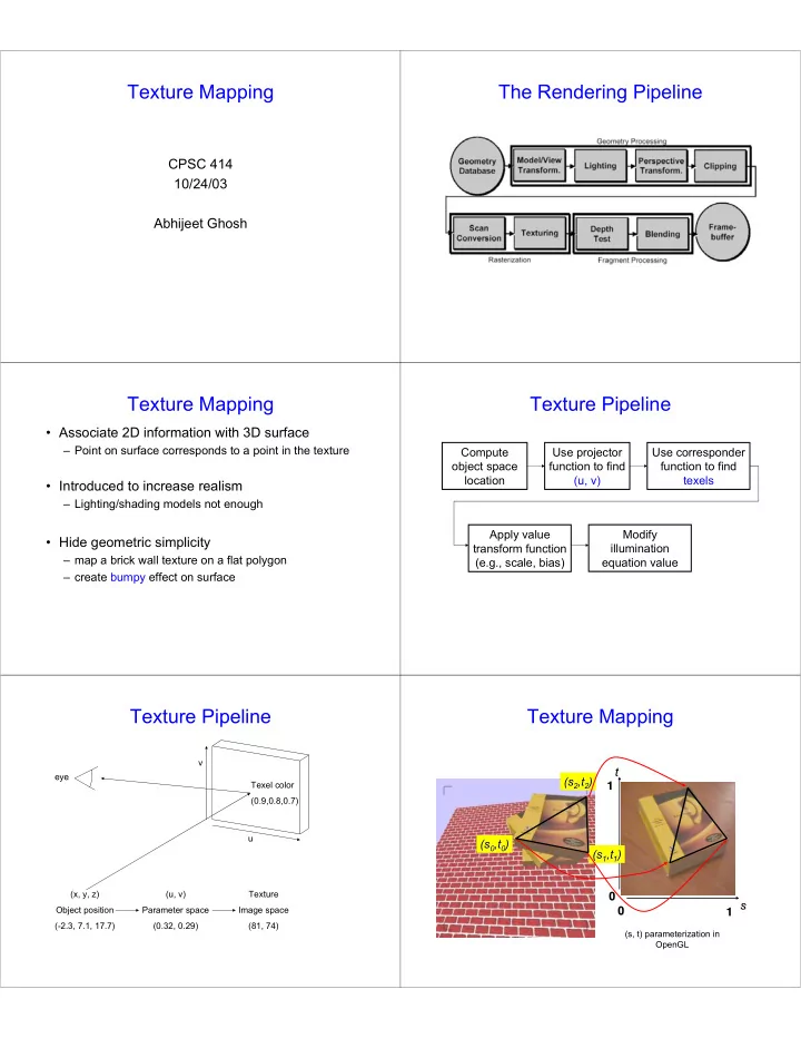
Texture Mapping

s s t t (s (s0

0,t

,t0

0)

) (s (s1

1,t

,t1

1)

) (s (s2

2,t

,t2

2)

) 1 1 1 1

(s, t) parameterization in OpenGL

slide-2
SLIDE 2

Texture Mapping

  • Texture Coordinates

– generation at vertices

  • specified by programmer or artist

glTexCoord2f(s,t) glVertexf(x,y,z)

  • generate as a function of vertex coords

glTexGeni(), glTexGenfv() s = a*x + b*y + c*z + d*h

– interpolated across triangle (like R,G,B,Z)

  • …well not quite!

Texture Mapping

  • Texture Coordinate Interpolation

– perspective foreshortening problem – also problematic for color interpolation, etc.

Attribute Interpolation

Bilinear Interpolation Incorrect Perspective correct Correct

Texture Coordinate Interpolation

  • Perspective Correct Interpolation

– α, β, γ :

  • Barycentric coordinates of a point P in a triangle

– s0, s1, s2 : texture coordinates – w0, w1,w2 : homogeneous coordinates

2 1 2 2 1 1

/ / / / / / w w w w s w s w s s γ + β + α ⋅ γ + ⋅ β + ⋅ α =

2 1 2 2 1 1

/ / / / / / w w w w s w s w s s γ + β + α ⋅ γ + ⋅ β + ⋅ α =

Texture Mapping

  • Textures of other dimensions

– 3D: solid textures

  • e.g.: wood grain, medical data, ...
  • glTexCoord3f(s,t,r)

– 4D: 3D + time, projecting textures

  • glTexCoord3f(s,t,r,q)

Texture Coordinate Transformation

  • Motivation:

– Change scale, orientation of texture on an object

  • Approach:

– texture matrix stack – 4x4 matrix stack – transforms specified (or generated) tex coords glMatrixMode( GL_TEXTURE ); glLoadIdentity(); …

slide-3
SLIDE 3

Texture Coordinate Transformation

  • Example:

(0,0) (0,0) (1,0) (1,0) (0,1) (0,1) (1,1) (1,1)

glScalef(4.0,4.0,?); glScalef(4.0,4.0,?);

(0,0) (0,0) (4,0) (4,0) (0,4) (0,4) (4,4) (4,4)

Texture Lookup

  • Issue:

– What happens to fragments with s or t outside the interval [0…1]? Multiple choices: – Take only fractional part of texture coordinates

  • Cyclic repetition of texture to tile whole surface

glTexParameteri( …, GL_TEXTURE_WRAP_S, GL_REPEAT )

– Clamp every component to range [0…1]

  • Re-use color values from border of texture image

glTexParameteri( …, GL_TEXTURE_WRAP_S, GL_CLAMP )

Texture Functions

  • Once got value from the texture map, can:

– Directly use as surface color GL_REPLACE – Modulate surface color GL_MODULATE – Blend surface and texture colors GL_DECAL – Blend surface color with another GL_BLEND

  • Specific action depends on internal texture format

– Only existing channels used

  • Specify with glTexEnvi(GL_TEXTURE_ENV,

GL_TEXTURE_ENV_MODE, mode)

Reconstruction

– How to deal with:

  • pixels that are much larger

than texels ? – apply filtering, “averaging”

  • pixels that are much smaller

than texels ?

– interpolate

Mip-mapping

Without MIP Without MIP-

  • mapping

mapping With MIP With MIP-

  • mapping

mapping

Use an “image pyramid” to pre-compute averaged versions of the texture

Mip-mapping

Problem:

  • A MIP-map level selects the same minification factor

for both the s and the t direction (isotropic filtering)

  • In reality, perspective foreshortening (amongst other

reasons) can cause different scaling factors for the two directions

slide-4
SLIDE 4

Mip-mapping

  • Which resolution to choose:

– MIP-mapping: take resolution corresponding to the smaller

  • f the sampling rates for s and t
  • Avoids aliasing in one direction at cost of blurring in the other

direction

– Better: anisotropic texture filtering

  • Also uses MIP-map hierarchy
  • Choose larger of sampling rates to select MIP-map level
  • Then use more samples for that level to avoid aliasing
  • Maximum anisotropy (ratio between s and t sampling rate) usually

limited (e.g. 4 or 8)

Texture Mapping Functions

Two Step Parameterization:

  • Step 1: map 2D texture onto an intermediate

simple surface

– Sphere – Cube – Cylinder

  • Step 2: map from this surface to the object

– Surface normal

  • Commonly used for environment mapping

Environment Mapping

reflective surface viewer environment texture image v n r

projector function converts reflection vector (x, y, z) to texture image (u, v)

Spherical Maps – Blinn & Newell ‘76

  • Transform reflection vector r into spherical coordinates

(θ, Ф)

– θ varies from [0, π] (latitude)

– Ф varies from [0, 2π] (longitude) r = (rx, ry, rz) = 2(n.v)n – v Θ = arccos(- rz) Ф = { arccos(- rx /sinΘ) if ry ≥ 0 { 2π - arccos(- rx /sinΘ) otherwise

Spherical Maps – Blinn & Newell ‘76

Slice through the photo Each pixel corresponds to particular direction in the environment

  • Singularity at the poles!
  • OpenGL support GL_SPHERE_MAP

Cube Mapping – Greene ‘86

A B C E F D

slide-5
SLIDE 5

Cube Mapping – Greene ‘86

  • Direction of reflection vector r selects the face of

the cube to be indexed

– Co-ordinate with largest magnitude

  • e.g., the vector (-0.2, 0.5, -0.84) selects the –Z face!

– Remaining two coordinates (normalized by the 3rd coordinate) selects the pixel from the face.

  • e.g., (-0.2, 0.5) gets mapped to (0.38, 0.80).
  • Difficulty in interpolating across faces!
  • OpenGL support GL_CUBE_MAP