TEXTURE MAPPING 1 OUTLINE Implementing Texturing What Can Go - - PowerPoint PPT Presentation

texture mapping
SMART_READER_LITE
LIVE PREVIEW

TEXTURE MAPPING 1 OUTLINE Implementing Texturing What Can Go - - PowerPoint PPT Presentation

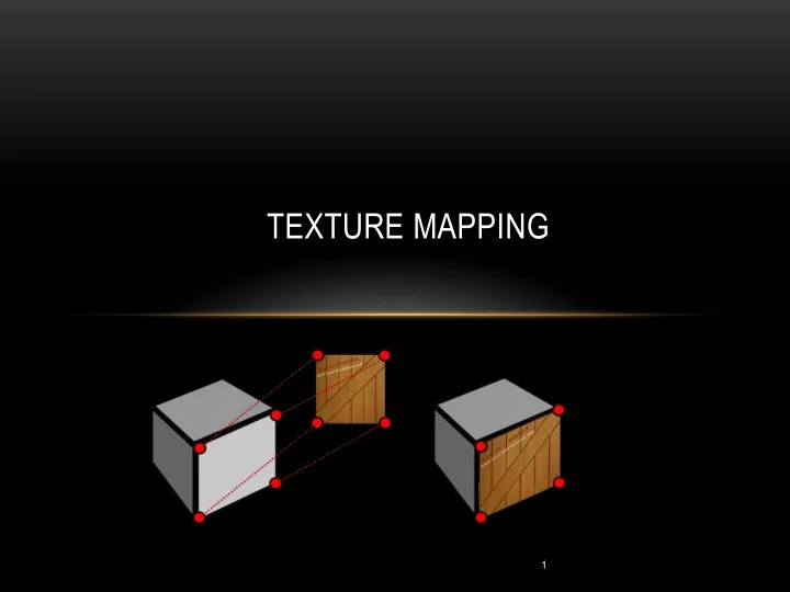
TEXTURE MAPPING 1 OUTLINE Implementing Texturing What Can Go Wrong and How to Fix It Mipmapping Filtering Perspective Correction 2 BASIC STRAGEGY Three steps to applying a texture 1. specify the texture read or


slide-1
SLIDE 1

1

TEXTURE MAPPING

slide-2
SLIDE 2

OUTLINE

  • Implementing Texturing
  • What Can Go Wrong and How to Fix It
  • Mipmapping
  • Filtering
  • Perspective Correction

2

slide-3
SLIDE 3

3

BASIC STRAGEGY

Three steps to applying a texture 1. specify the texture

  • read or generate image
  • assign to texture
  • enable texturing

2. assign texture coordinates to vertices

  • Proper mapping function is left to application

3. specify texture parameters

  • wrapping, filtering
slide-4
SLIDE 4

SPECIFY THE TEXTURE

  • Data and mechanisms needed:
  • A Texture object – to hold the texture image
  • Uniform sampler variable in the vertex shader – so shader can access texture
  • Buffer to hold texture coordinates
  • Vertex attribute to pass texture coordinates through pipeline
  • Texture unit on the graphics card
slide-5
SLIDE 5

TEXTURE OBJECT

  • The loadTexture method from the Java/JOGL example code

public Texture loadTexture(String textureFileName) { Texture tex = null; try { tex = TextureIO.newTexture(new File(textureFileName), false); } catch (Exception e) { e.printStackTrace(); } return tex; }

slide-6
SLIDE 6

SETTING UP THE TEXTURE AS AN OPENGL TEXTURE

  • Instance variables:

private int brickTexture; private Texture joglBrickTexture;

  • In init():

joglBrickTexture = loadTexture("brick1.jpg"); brickTexture = joglBrickTexture.getTextureObject();

slide-7
SLIDE 7

TEXTURE COORDINATES

  • Need to specify texture coordinates for each vertex in our object(s)
  • Two buffers for each set of vertex coordinates
  • Vertex coordinates in 3D space (x, y, z)
  • Texture coordinates in 2D space (s, t)
  • Assumption is that texture image is rectangular with 0, 0 in the lower left

and 1,1 in the upper right.

  • Coordinates should all be between 0 and 1
  • Texture coordinates are stored in a vertex attribute so they are also interpolated by the

rasterizer

  • Difficult to specify by hand for complex objects
  • If built in an object modeling tool, often they provide “UV-mapping” for this purpose
slide-8
SLIDE 8

TEXTURE MAPPING GONE WRONG

We saw this mapping last time – specifying coordinates incorrectly can have bad results

slide-9
SLIDE 9

TEXTURE MAPPING

Specifying them correctly can look realistic

slide-10
SLIDE 10

TEXTURE MAPPING – THE PYRAMID

Vertices Texture Coordinates

  • 1.0
  • 1.0

1.0 front face 1.0

  • 1.0

1.0 1 0.0 1.0 0.0 .5 1 1.0

  • 1.0

1.0 right face 1.0

  • 1.0
  • 1.0

1 0.0 1.0 0.0 .5 1 1.0

  • 1.0
  • 1.0

back face

  • 1.0
  • 1.0
  • 1.0

1 0.0 1.0 0.0 .5 1 …

slide-11
SLIDE 11

TEXTURE MAPPING – THE PYRAMID CODE, SETUPVERTICES() METHOD

float[] pyramid_positions = {-1.0f, -1.0f, 1.0f, 1.0f, -1.0f, 1.0f, 0.0f, 1.0f, 0.0f, //front 1.0f, -1.0f, 1.0f, 1.0f, -1.0f, -1.0f, 0.0f, 1.0f, 0.0f, //right 1.0f, -1.0f, -1.0f, -1.0f, -1.0f, -1.0f, 0.0f, 1.0f, 0.0f, //back

  • 1.0f, -1.0f, -1.0f, -1.0f, -1.0f, 1.0f, 0.0f, 1.0f, 0.0f, //left
  • 1.0f, -1.0f, -1.0f, 1.0f, -1.0f, 1.0f, -1.0f, -1.0f, 1.0f, //LF

1.0f, -1.0f, 1.0f, -1.0f, -1.0f, -1.0f, 1.0f, -1.0f, -1.0f //RR }; float[] texture_coordinates = {0.0f, 0.0f, 1.0f, 0.0f, 0.5f, 1.0f, 0.0f, 0.0f, 1.0f, 0.0f, 0.5f, 1.0f, 0.0f, 0.0f, 1.0f, 0.0f, 0.5f, 1.0f, 0.0f, 0.0f, 1.0f, 0.0f, 0.5f, 1.0f, 0.0f, 0.0f, 1.0f, 1.0f, 0.0f, 1.0f, 1.0f, 1.0f, 0.0f, 0.0f, 1.0f, 0.0f };

slide-12
SLIDE 12

LOADING TEXTURE COORDINATES INTO BUFFERS

  • Instance variables:

private int vao[] = new int[1]; private int vbo[] = new int[2];

  • In display():

gl.glBindBuffer(GL_ARRAY_BUFFER, vbo[0]); gl.glVertexAttribPointer(0, 3, GL_FLOAT, false, 0, 0); gl.glEnableVertexAttribArray(0); gl.glBindBuffer(GL_ARRAY_BUFFER, vbo[1]); gl.glVertexAttribPointer(1, 2, GL_FLOAT, false, 0, 0); gl.glEnableVertexAttribArray(1);

slide-13
SLIDE 13

GLSL CODE

  • Vertex shader needs coordinates
  • Fragment shader needs access to the texture object
slide-14
SLIDE 14

VERTEX SHADER

#version 430 layout (location=0) in vec3 pos; layout (location=1) in vec2 texCoord;

  • ut vec2 tc;

uniform mat4 mv_matrix; uniform mat4 proj_matrix; layout (binding=0) uniform sampler2D samp; void main(void) { gl_Position = proj_matrix * mv_matrix * vec4(pos,1.0); tc = texCoord; }

slide-15
SLIDE 15

FRAGMENT SHADER

#version 430 in vec2 tc;

  • ut vec4 color;

uniform mat4 mv_matrix; uniform mat4 proj_matrix; layout (binding=0) uniform sampler2D samp; void main(void) { color = texture(samp, tc); }

slide-16
SLIDE 16

BACK TO JAVA/JOGL CODE

  • After binding buffers with vertices and texture coordinates in display():

gl.glActiveTexture(GL_TEXTURE0); gl.glBindTexture(GL_TEXTURE_2D, brickTexture);

  • Recall that brickTexture is an integer that holds the pointer to the OpenGL texture object

we created in init()

slide-17
SLIDE 17

WHAT CAN GO WRONG

  • Differences between texture image size and object image size
  • Texture image resolution less than that of object
  • Can stretch texture across image region
  • May become blurry and possibly distorted
  • Texture image resolution higher than that of object
  • Aliasing – caused by sampling errors
  • Can cause false patterns or shimmering in moving objects
slide-18
SLIDE 18

WHAT CAN GO WRONG

False patterns Shimmering

slide-19
SLIDE 19

MIPMAPPING

  • Can often correct aliasing errors
  • Different versions (sizes) of the image stored in the texture buffer
  • The one closest to the size of the region is used for texturing
  • Separate RGB versions of the image are stored at each resolution
  • Several ways to sample a mipmap
  • GL_NEAREST_MIPMAP_NEAREST
  • GL_LINEAR_MIPMAP_NEAREST
  • GL_NEAREST_MIPMAP_LINEAR
  • GL_LINEAR_MIPMAP_LINEAR
slide-20
SLIDE 20

MIPMAPPING

Linear filtering (GL_LINEAR_MIPMAP_NEAREST) Trilinear filtering (GL_LINEAR_MIPMAP_LINEAR)

slide-21
SLIDE 21

MIPMAPPING

  • In the Java/JOGL code, after loading the texture object:

gl.glBindTexture(GL_TEXTURE_2D, brickTexture); gl.glTexParameteri(GL_TEXTURE_2D, GL_TEXTURE_MIN_FILTER, GL_LINEAR_MIPMAP_LINEAR); gl.glGenerateMipmap(GL.GL_TEXTURE_2D);

slide-22
SLIDE 22

FILTERING

  • Mipmapped images can appear more blurry
  • Anisotropic filtering uses rectangular resolutions of the image as well as the square

versions in mipmapping

  • More computationally expensive (of course)
  • Java/JOGL code in init():

if (gl.isExtensionAvailable("GL_EXT_texture_filter_anisotropic")) { float anisoset[] = new float[1]; gl.glGetFloatv(GL_MAX_TEXTURE_MAX_ANISOTROPY_EXT, anisoset, 0); gl.glTexParameterf(GL_TEXTURE_2D, GL_TEXTURE_MAX_ANISOTROPY_EXT, anisoset[0]); }

slide-23
SLIDE 23

PERSPECTIVE CORRECTION

  • OpenGL applies perspective correction

by default

  • Corrects for distortion caused by

perspective projection

  • If you don’t want this, can turn

it off by including the following in both the vertex and fragment shaders:

noperspective out vec2 texCoord;

slide-24
SLIDE 24

SUMMARY

  • Implementing Texturing
  • What Can Go Wrong and How to Fix It
  • Mipmapping
  • Filtering
  • Perspective Correction

24