strain behaviour of cfrp high pressure vessel during
play

STRAIN BEHAVIOUR OF CFRP HIGH PRESSURE VESSEL DURING MANUFACTURING - PDF document

18 TH INTERNATIONAL CONFERENCE ON COMPOSITE MATERIALS STRAIN BEHAVIOUR OF CFRP HIGH PRESSURE VESSEL DURING MANUFACTURING PROCESS T. Kosaka 1* , K. Osaka 2 , J. Suzuki 3 , Y. Sawada 2 1 Dept. Systems Engineering, Kochi University of Technology,


  1. 18 TH INTERNATIONAL CONFERENCE ON COMPOSITE MATERIALS STRAIN BEHAVIOUR OF CFRP HIGH PRESSURE VESSEL DURING MANUFACTURING PROCESS T. Kosaka 1* , K. Osaka 2 , J. Suzuki 3 , Y. Sawada 2 1 Dept. Systems Engineering, Kochi University of Technology, Kami-City, Kochi, Japan, 2 Graduate School of Engineering, Osaka City University, Osaka, Japan 3 SAMTECH Co., Ltd, Kashiwara-City, Osaka, Japan * Corresponding author(kosaka.tatsuro@kochi-tech.ac.jp) Keywords : Pressure vessel, Autofrettage process, Strain monitoring, CFRP, manufacturing process monitoring 1 Introduction A hydrogen automobile is promised to be a next- generation eco-car for reduction of greenhouse gas. In order to extend range of hydrogen cars, a very- high pressure vessel has been developed recent years. A CFRP high pressure vessel, which is made by combination of an aluminum liner and CFRP layers, is a most promising technology for hydrogen cars[1]. Manufacturing process of the pressure vessel has filament winding (FW) process of carbon fibers, cure process, cooling process and autofrettage process. During these manufacturing processes or 
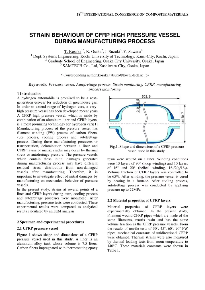
transportation, delamination between a liner and Fig.1. Shape and dimensions of a CFRP pressure CFRP layers or matrix cracks may occur by thermal vessel used in this study. stress or autofrettage pressure. The pressure vessels which contain these initial damages generated resin were wound on a liner. Winding conditions during manufacturing process may have different were 13 layers of 90° (hoop winding) and 10 layers residual stress distribution from non-damaged of 16° and 20° (helical winding, 16 4 /20 2 /16 4 ). vessels after manufacturing. Therefore, it is Volume fraction of CFRP layers was controlled to important to investigate effect of initial damages by be 65%. After winding, the pressure vessel is cured manufacturing on mechanical behavior of pressure by heating in a furnace. After cooling process, vessels. autofrettage process was conducted by applying In the present study, strains at several points of a pressure up to 72MPa. liner and CFRP layers during cure, cooling process and autofrettage processes were monitored. After 2.2 Material properties of CFRP layers manufacturing, pressure tests were conducted. These experimental results were compared to analytical Material properties of CFRP layers were results calculated by an FEM analysis. experimentally obtained. In the present study, Filament wound CFRP pipes which are made of the same filaments, matrix resin and has the same 2 Specimen and experimental procedures volume fraction as the CFRP pressure vessels. From 2.1 CFRP pressure vessel the results of tensile tests of 30°, 45°, 60°, 90° FW pipes, mechanical constants of unidirectional CFRP Figure 1 shows shape and dimensions of a CFRP were obtained. Thermal strains were also measured pressure vessel used in this study. A liner is an by thermal loading tests from room temperature to aluminum alloy tank whose volume is 7.5 liters. 140°C. These materials constants were shown in Carbon fibers impregnated with thermosetting epoxy Table 1.

  2. Table.1 Properties of unidirectional CFRP [6]) and CFRP layers (CF[1]-[6]) in order to E L (GPa) 191.9 measure meridian and circumferential strains as shown in Fig. 2. Strain gages were also adhered at E T (GPa) 8.7 the opposite side (180° from the other side around G LT (GPa) 5.34 ν L center axis of the tank). Sensor positions were 0.29 defined as a distance from the edge of inlet/outlet α L ( µε /°C) 2.68 port. Sensors No.1~5 were at the dome part and α T ( µε /°C) 32.67 sensors No.6 were at center of the cylinder part. Only strains of the liner were measured at cooling process. After cooling, strain gages were adhered on the surface of CFRP. Then, both strains of the liner and CFRP were monitored during autofrettage process and pressure tests. Figure 3 shows an experimental set-up for measuring strain and pressure during autofrettage process and pressure tests. Applied pressure was measured by a presser sensor and collected by a data logger with strain data of the pressure vessel. In the autofrettage process, pressure was increased from 0MPa to 72 MPa with a rate of 5.4 MPa/min., kept Distance from inlet/outlet port edge (unit: mm) for 2 minutes, and then decreased to 0 MPa. In the No. Al[ ] CF[ ] pressure test, pressure was increased from 0MPa to 1 34 25 52 MPa with a rate of 7.8 MPa/min. 2 38 33.5 3 45 43.3 4 58 57 3 Experimental results and discussions 5 74 74 3.1 Thermal strain of liner during cooling process 6 252 252 Thermal strain of the aluminum liner was measured Fig.2. Positions of strain gauges. during cooling process. Strains at Al[2] are plotted against temperature in Fig.4. From the figure, it can Pump be clearly seen that a relationship between strain of hose the liner and temperature show bilinearity at 70°C. inlet/outlet Strains at Al[1]-[5] except Al[6] showed such bilinear behavior by cooling after heating cure Pressure sensor Strain process. The figure 5 shows CTEs (Coefficients of gages Vessel thermal expansion) of meridian strain at all positions. From the figure, it was found that CTEs of Al[1]-[5] under 70°C were almost the same as CTE of aluminum ally (23.6 µε /°C). These experimental results showed delamination between the liner and CFRP layers occurred at dome part of the pressure PC Data logger vessel. However, it can be considered that the Fig.3 Experimental set-up for measuring strain and delamination occurred partially since constrained pressure during autofrettage process and pressure strain of the linear by CFRP layer was not released test. as shown in Fig.4. On the other hand, CTE of Al[6] was almost constant from 134°C to 29°C but sudden 2.3 Sensors and experimental set-up small decrease by -200 µε could be seen at 29°C. Therefore, it can be thought that the delamination In the present study, 2-axial strain gauges were area distributed in the cylinder part is small. adhered on the surface of the aluminum liner (Al[1]-

  3. PAPER TITLE 80 0 CF[3] 70 Inner pressure (MPa) CF[4] 60 -500 CF[5] 50 Strain ( µε ) 40 -1000 30 20 -1500 10 0 -2000 20 40 60 80 100 120 140 -1000 0 1000 2000 3000 4000 5000 Temperature (°C) Strain ( µε ) Fig.6 Relationships between applied pressure and Fig.4 Temperature – strain (Al[2]) curve during meridian strain of CFRP layers during autofrettage cooling process. process (CF[3],[4],[5]). 80 0°:134 - 70°C 180°:134 - 70°C AL[3] 70 0°: 70 - 25°C 180°: 70 - 25°C AL[4] Inner pressure (MPa) 30 60 AL[5] 50 25 40 20 CTE ( µε /°C) 30 20 15 10 10 0 -500 0 500 1000 1500 2000 2500 3000 5 Strain ( µε ) Fig.7 Relationships between applied pressure and 0 meridian strain of aluminum liner during 0 1 2 3 4 5 6 7 autofrettage process (Al[3],[4],[5]). Strain gage number Al[ ] 80 Fig.5 Thermal coefficient of meridian strain of the CF[6] 70 liner during cooling process. Inner pressure (MPa) 60 50 3.2 Strain measurement during autofrettage 40 process 30 Strains of the liner and CFRP layers were monitored 20 during autofrettage process. Figures 6 and 7 show 10 pressure-strain curves for meridian strains CF[3]-[5] 0 of the CFRP layers and Al[3]-[5] of the liner, -1000 0 1000 2000 3000 4000 5000 6000 respectively. From the experimental results of Fig.6, Strain ( µε ) it was found that the strain behavior of CFRP layers Fig.8 Pressure- axial strain curve during autofrettage showed strong nonlinearity when pressure increasing process (CF[6]). during autofrettage process. The variation of meridian strains was very small when the applied considered that this low strain sensitivity of the pressure was lower than about 10MPa. On the other CFRP dome to pressure under 10MPa was caused by hand, the figure 7 showed monotonic increase of delamination gaps between the liner and CFRP layer strain by increasing pressure. Therefore, it was generated during cooling process. When pressure 3

Download Presentation
Download Policy: The content available on the website is offered to you 'AS IS' for your personal information and use only. It cannot be commercialized, licensed, or distributed on other websites without prior consent from the author. To download a presentation, simply click this link. If you encounter any difficulties during the download process, it's possible that the publisher has removed the file from their server.

Recommend


More recommend