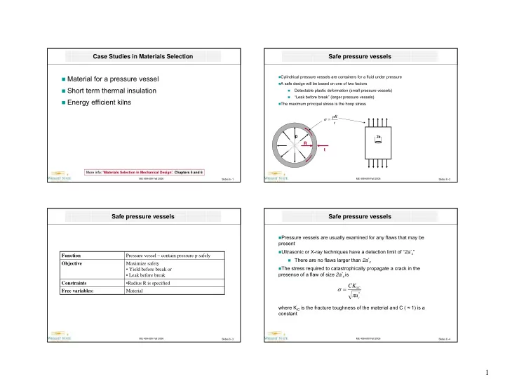
1
play

1 Safe pressure vessels Safe pressure vessels Therefore, for - PowerPoint PPT Presentation

Case Studies in Materials Selection Safe pressure vessels Material for a pressure vessel Cylindrical pressure vessels are containers for a fluid under pressure A safe design will be based on one of two factors Short term thermal


  1. Case Studies in Materials Selection Safe pressure vessels � Material for a pressure vessel � Cylindrical pressure vessels are containers for a fluid under pressure � A safe design will be based on one of two factors � Short term thermal insulation Detectable plastic deformation (small pressure vessels) � “Leak before break” (larger pressure vessels) � � Energy efficient kilns � The maximum principal stress is the hoop stress pR σ = t p 2a R t More info: “ Materials Selection in Mechanical Design ”, Chapters 5 and 6 ME 499-699 Fall 2006 ME 499-699 Fall 2006 Slides 6 -1 Slides 6 -2 Safe pressure vessels Safe pressure vessels � Pressure vessels are usually examined for any flaws that may be present � Ultrasonic or X-ray techniques have a detection limit of “ 2a * c ” Function Pressure vessel – contain pressure p safely � There are no flaws larger than 2a * c Objective Maximize safety � The stress required to catastrophically propagate a crack in the • Yield before break or presence of a flaw of size 2a * c is • Leak before break Constraints •Radius R is specified CK σ = 1 C Free variables: Material π * a c where K iC is the fracture toughness of the material and C ( ≈ 1) is a constant ME 499-699 Fall 2006 ME 499-699 Fall 2006 Slides 6 -3 Slides 6 -4 1

  2. Safe pressure vessels Safe pressure vessels � Therefore, for safety � However, if one wanted to ensure that the material yielded before fracture, then it should be possible to reach the failure stress or yield stress even when the flaw size is greater than the detection limit of the NDE technique t t K = σ ≤ p 1 C π R R * a 2 ⎡ ⎤ c K π ≤ ⎢ ⎥ 2 1 C a C c σ ⎢ ⎥ ⎣ ⎦ � The corresponding material index to be maximized is f � In order to maximize the flaw size for with “yield before break” occurs, the material index to be maximized is 1 = M K 1 C K 2 = 1 C M σ f ME 499-699 Fall 2006 ME 499-699 Fall 2006 Slides 6 -5 Slides 6 -6 Safe pressure vessels Safe pressure vessels � It may not be possible to subject a large pressure vessels to complete X- ray or ultrasonic examination to locate pre-existing flaws � Material indices M 2 and M 3 indicate σ f should be as small � Therefore, if the vessel is designed such that critical flaw size ( 2a c ) is at as possible. least equal to the thickness of the wall the even when the stress reaches the � A material like lead would satisfy these indices yield stress, then the vessel will “leak before break” 2 � However, if one wanted to make a thin walled pressure ⎛ ⎞ ⎛ ⎞ 2 t C ⎜ K ⎟ = ⎜ ⎟ 1 C ⎜ ⎟ π σ ⎝ ⎠ vessel, the thinnest wall is obtained by having a high value 2 ⎝ ⎠ f pR of the yield strength. σ = t � Therefore, there is a fourth index that needs to be or ⎛ ⎞ 2 2 2 C K maximized. Namely = ⎜ ⎟ p 1 C π σ ⎝ ⎠ R f M 4 = σ f � Under this situation, the material index to be maximized is � The following slides show the successive application of each of the indices to select a material 2 K 3 = 1 C M σ f ME 499-699 Fall 2006 ME 499-699 Fall 2006 Slides 6 -7 Slides 6 -8 2

  3. Safe pressure vessels Safe pressure vessels 1e8 1e8 M 1 M 2 1e7 1e7 K 1C > 10 MPa.m 0.5 Fracture toughness (Pa.m^1/2) Fracture toughness (Pa.m^1/2) 1e6 1e6 100000 100000 10000 10000 10000 100000 1e6 1e7 1e8 1e9 10000 100000 1e6 1e7 1e8 1e9 Yield strength (elastic limit) (Pa) Yield strength (elastic limit) (Pa) ME 499-699 Fall 2006 ME 499-699 Fall 2006 Slides 6 -9 Slides 6 -10 Safe pressure vessels Safe pressure vessels Commercially pure zinc Copper 1e8 M 4 100 Non age-hardening wrought Al-alloys Cast Al-alloys M 3 1e7 10 Fracture toughness (MPa.m^1/2) Zinc die-casting alloys Fracture toughness (Pa.m^1/2) 1e6 1 Stainless steel Bronze 0.1 100000 0.01 10000 0.01 0.1 1 10 100 1000 10000 100000 1e6 1e7 1e8 1e9 Yield strength (elastic limit) (MPa) Yield strength (elastic limit) (Pa) ME 499-699 Fall 2006 ME 499-699 Fall 2006 Slides 6 -11 Slides 6 -12 3

  4. Safe pressure vessels Short term thermal insulation Commercially pure zinc Copper 1e8 � An application for short term thermal insulation is the rescue beacons for military aircraft pilots All stages Non age-hardening wrought Al-alloys Cast Al-alloys � These electronic devices do not function if the temperature drops below a critical value 1e7 � Therefore, to give the rescue operation the greatest chance of being effective, Zinc die-casting alloys Fracture toughness (Pa.m^1/2) the temperature of the electronics in the radio beacon must not fall below a critical value for the longest period of time even when exposed to cold 1e6 Stainless steel temperatures The temperature of most of the earth’s oceans is around 4ºC Bronze � � The electronics have to be wrapped in an insulating blanket 100000 10000 10000 100000 1e6 1e7 1e8 1e9 Yield strength (elastic limit) (Pa) ME 499-699 Fall 2006 ME 499-699 Fall 2006 Slides 6 -13 Slides 6 -14 Short term thermal insulation Short term thermal insulation � Model 1 � Minimize heat flux out of the containment area Function Short term thermal insulation � First law of heat conduction Objective Maximize time before which internal temperature drops below critical value ( ) i − dT T T = − λ ≈ λ o q Constraints Wall thickness must not exceed w dx w Free variables: Material � Where q is heat flux, λ is thermal conductivity � Therefore, minimize λ to minimize heat flow Insulating material of wall thickness w � Best materials are polymer foams Electronic circuits packaged in this space ME 499-699 Fall 2006 ME 499-699 Fall 2006 Slides 6 -15 Slides 6 -16 4

  5. Short term thermal insulation Short term thermal insulation � But is this the answer we are looking for? � The answer is no! 100 � The problem requires that the time that it takes for the electronic package to cool down be maximized. � This is not a steady state problem. Thermal conductivity (W/m.K) 10 � Therefore use 2 nd law of heat conduction � If the temperature at the surface is decreased suddenly, as in dropping the pilot and his radio beacon into a cold ocean, the distance x from the surface at which a 1 certain temperature is reached changes with time t as ∝ x 2 at Cork � Where a is the thermal diffusivity Flexible Polymer Foam (MD) Rigid Polymer Foam (MD) 0.1 λ = a ρ C Rigid Polymer Foam (LD) p MaterialUniverse:\Ceramics and glasses MaterialUniverse:\Hybrids: composites, foams, natural materials MaterialUniverse:\Metals and alloys MaterialUniverse:\Polymers and elastomers Untitled ME 499-699 Fall 2006 ME 499-699 Fall 2006 Slides 6 -17 Slides 6 -18 Short term thermal insulation Short term thermal insulation � ρ is the density and C p is the specific heat of the material. 100 � We can replace x in the above equation by the wall thickness to get 2 Polymethyl methacrylate (Acrylic, PMMA) w ≈ t 2 a Thermal conductivity (W/m.K) 10 � Therefore, we seek the material with the smallest a to maximize the Isoprene (IR) time t , if the thickness of the insulation w is fixed � The best materials are therefore elastomers Isoprene (IR) 1 Rigid Polymer Foam (HD) 0.1 Isoprene (IR) 1e-7 1e-6 1e-5 1e-4 T-diffusivity ME 499-699 Fall 2006 ME 499-699 Fall 2006 Slides 6 -19 Slides 6 -20 5

  6. Energy efficient kiln Energy efficient kiln � Kilns used for firing pottery are heated up from room temperature to the firing � How can these apparently contradictory requirements be reconciled? temperature during each cycle � Is there a material index that can capture both requirements? Unbaked pottery is placed in the furnace Wall thickness w � The heating mechanism, electric or gas, is turned on and the kiln is � heated up to the firing temperature After the requisite time at temperature, the kiln is allowed to cool down � Insulation Once cooled, the pottery is removed and the cycle is repeated � T-con λ � There are two major factors that consume energy Density ρ The energy to heat up the kiln � T o T i Sp-heat C p The energy lost through conduction through the walls � � The first can be minimized by reducing the thermal mass of the system, i.e. minimize the wall thickness � The second can be minimized by reducing the heat loss through the wall by increasing its thickness ME 499-699 Fall 2006 ME 499-699 Fall 2006 Slides 6 -21 Slides 6 -22 Energy efficient kiln Energy efficient kiln Analysis � There are two sources of heat loss Function Thermal insulation for kiln (cyclic Heat lost by conduction through walls � heating and cooling) i − dT T T = − λ = λ Q t o t Objective Minimize energy consumed in each cycle 1 dx w Hard: Max operating temp = 1000 ° C Constraints Heat required to increase temperature of insulating material � Soft: Wall thickness due to space ( ) − T T = ρ i o limitation Q C w 2 p 2 Free variables: Material Total heat loss is Wall thickness � ( ) − − T T T T = + = λ + ρ i o i o Q Q Q t C w 1 2 p w 2 ME 499-699 Fall 2006 ME 499-699 Fall 2006 Slides 6 -23 Slides 6 -24 6

Recommend


More recommend