
SLIDE 1
RF Reference Distribution System for the RISP Linac
Kyungtae Seol, Doyoon Lee, Hyojae Jang, Ohryong Choi, Kitaek Son Rare Isotope Science Project, Institute for Basic Science, Daejeon 34000, Korea
*Corresponding author: ktseol@ibs.re.kr
- 1. Introduction
The heavy-ion accelerator of the Rare Isotope Science Project (RISP) in Korea has been developed [1- 2]. The RF reference distribution system must deliver a phase reference signals to all low-level RF (LLRF) systems and BPM systems with low phase noise and low phase drift. The frequencies of RISP linac are 81.25MHz, 162.5MHz and 325MHz, and there are 130 LLRF systems and 60 BPMs respectively for SCL3, and 210 LLRF systems and 60 BPMs for SCL2. 81.25 MHz signal is chosen as an reference frequency, and 1- 5/8“ rigid coaxial line is installed with temperature
- control. This paper describes the design for the RF
reference distribution system such as reference frequency, phase noise on master oscillator, phase stability and temperature influence, and reference line attenuation.
- 2. RF reference distribution
2.1 Conceptual Design There are a variety of approaches to distribute the RF reference signals and many new technologies are being applied worldwide [3-5]. As coaxial-cable-based distribution and optical-fiber-based distribution are the two most commonly used solutions for RF reference distribution in Linac. Coaxial cable is a very conventional medium to distribute the RF reference signal, by which RF signal can be transmitted directly from source to destinations [6]. For a linac with multiple LLRF systems, a bus-like topology is preferred with a main cable line running the RF power and many tap points along the line delivering required signals to each
- f LLRF systems. The bus-like topology distribution has
the advantage of less volume, less power attenuation and easier to implement compared to star topology. The requirements of the RF phase stability is ±1° in RF control system, and phase stability in RF reference should be within ±0.3° commonly to satisfy the
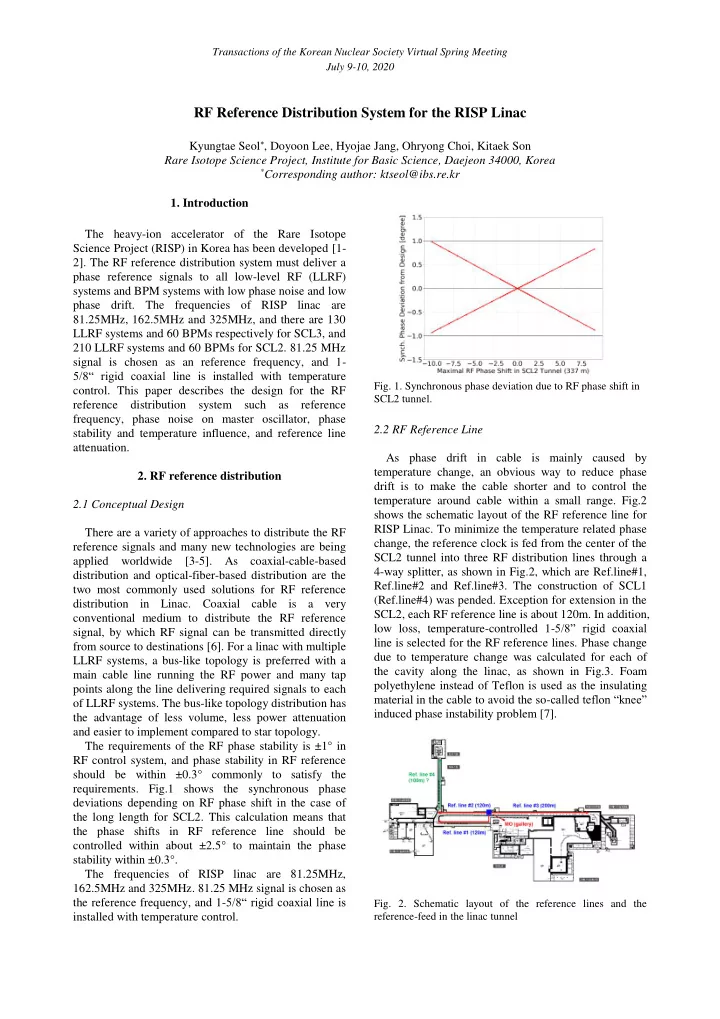
- requirements. Fig.1 shows the synchronous phase
deviations depending on RF phase shift in the case of the long length for SCL2. This calculation means that the phase shifts in RF reference line should be controlled within about ±2.5° to maintain the phase stability within ±0.3°. The frequencies of RISP linac are 81.25MHz, 162.5MHz and 325MHz. 81.25 MHz signal is chosen as the reference frequency, and 1-5/8“ rigid coaxial line is installed with temperature control.
- Fig. 1. Synchronous phase deviation due to RF phase shift in
SCL2 tunnel.
2.2 RF Reference Line As phase drift in cable is mainly caused by temperature change, an obvious way to reduce phase drift is to make the cable shorter and to control the temperature around cable within a small range. Fig.2 shows the schematic layout of the RF reference line for RISP Linac. To minimize the temperature related phase change, the reference clock is fed from the center of the SCL2 tunnel into three RF distribution lines through a 4-way splitter, as shown in Fig.2, which are Ref.line#1, Ref.line#2 and Ref.line#3. The construction of SCL1 (Ref.line#4) was pended. Exception for extension in the SCL2, each RF reference line is about 120m. In addition, low loss, temperature-controlled 1-5/8” rigid coaxial line is selected for the RF reference lines. Phase change due to temperature change was calculated for each of the cavity along the linac, as shown in Fig.3. Foam polyethylene instead of Teflon is used as the insulating material in the cable to avoid the so-called teflon “knee” induced phase instability problem [7].
- Fig. 2. Schematic layout of the reference lines and the