SLIDE 1
2.6 Proton Linac
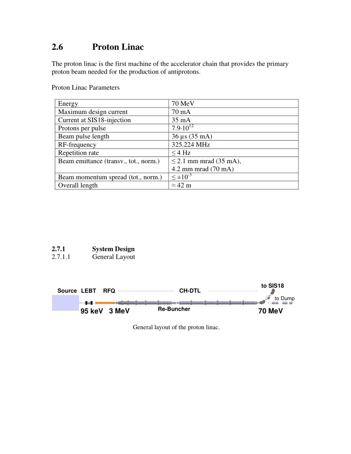
The proton linac is the first machine of the accelerator chain that provides the primary proton beam needed for the production of antiprotons. Proton Linac Parameters Energy 70 MeV Maximum design current 70 mA Current at SIS18-injection 35 mA Protons per pulse 7.9·1012 Beam pulse length 36 µs (35 mA) RF-frequency 325.224 MHz Repetition rate ≤ 4 Hz Beam emittance (transv., tot., norm.) ≤ 2.1 mm mrad (35 mA), 4.2 mm mrad (70 mA) Beam momentum spread (tot., norm.) ≤ ±10-3 Overall length ≈ 42 m 2.7.1 System Design 2.7.1.1 General Layout 95 keV 3 MeV 70 MeV
Source LEBT RFQ CH-DTL Re-Buncher
to Dump
to SIS18
General layout of the proton linac.
SLIDE 2 2.7.2 Magnets 2.7.2.1 Solenoid Magnets Physical parameters fixed Design/engineering fixed Integration/DMU check done Procurement start Procurement time Number of magnets 2 Normal or super conducting nc
T 0.76
T 0.0 Effective length, L m 0.263 Aperture radius mm 80
T/s dc Usable horizontal aperture mm 80 Usable vertical aperture mm 80 Integrated random field error BL/BL < 0.0005 Overall length m 0.31 Overall width m 0.550 Overall height m 0.550 Iron/copper weight kg tbd Overall weight t tbd Number of turns 288 Current at max field A tbd Inductance per magnet mH tbd Resistance per magnet tbd Power consumption kW tbd Coil copper cross section mm mm 125 x 240 Cooling channel diameter. mm 4.5 Cooling water flow rate l/min 34 Cooling water temp. rise K 12 Cooling water pressure drop bar 8.0
SLIDE 3 2.7.2.1.1 Steerer Magnets Type S1 Physical parameters fixed Design/engineering fixed Integration/DMU check done Procurement start Procurement time Number of magnets 2 Normal or super conducting nc
Tm 0.0015 Effective length, L m 0.08 Aperture radius mm 80
T/s dc Usable horizontal aperture mm 80 Usable vertical aperture mm 80 Integrated random field error BL/BL < 0.02 Overall length m 0.310 Overall width m 0.550 Overall height m 0.550 Iron/copper weight kg tbd Overall weight t tbd Number of turns 2*7 Current at max field A tbd Inductance per magnet mH tbd Resistance per magnet tbd Power consumption kW tbd Coil copper cross section mm mm 6x6 Cooling channel diameter. mm Cooling water flow rate l/min Cooling water temp. rise K
- Cooling water pressure drop
bar
SLIDE 4 2.7.2.2.2 Steerer Magnets Type S2 Physical parameters fixed Design/engineering fixed Integration/DMU check done Procurement start Procurement time Number of magnets 5 Normal or super conducting nc
Tm 0.0125 Effective length, L m
mm 20
T/s Bmax / 25 ms Usable horizontal aperture mm 20 Usable vertical aperture mm 20 Overall length m 0.1 Overall width m tbd Overall height m tbd Iron/copper weight kg tbd Overall weight t tbd Number of turns tbd Current at max field A tbd Inductance per magnet mH tbd Resistance per magnet tbd Power consumption kW tbd Coil copper cross section mm mm tbd Cooling channel diameter. mm tbd Cooling water flow rate l/min tbd Cooling water temp. rise K tbd Cooling water pressure drop bar tbd
SLIDE 5 2.7.2.3.3 Quadrupole Magnets Type C Physical parameters fixed Design/engineering fixed Integration/DMU check done Procurement start Procurement time Number of magnets 24 Normal or super conducting nc
T/m 72
T/m 3.35 Effective length, L m 0.084 Aperture radius mm 15
T/ms 2880 Usable horizontal aperture mm 15 Usable vertical aperture mm 15 Overall length m 0.089 Overall width m 0.180 Overall height m 0.180 Iron/copper weight kg tbd Overall weight t 0.017 Number of turns per pole 8 Current at max field A 946 Inductance per magnet mH 0.213 Resistance per magnet 0.027 Power consumption kW 24.3 Coil copper cross section mm mm tbd Cooling channel diameter. mm tbd Cooling water flow rate l/min 4.8 Cooling water temp. rise K 25 Cooling water pressure drop bar 2.6 2.7.2.3.4 Quadrupole Magnets Type D
SLIDE 6 Physical parameters fixed Design/engineering fixed Integration/DMU check done Procurement start Procurement time Number of magnets 11 Normal or super conducting nc
T/m 72.8
T/m 3.35 Effective length, L m 0.046 Aperture radius mm 15
T/ms 2912 Usable horizontal aperture mm 15 Usable vertical aperture mm 15 Overall length m 0.051 Overall width m 0.180 Overall height m 0.180 Iron/copper weight kg tbd Overall weight t 0.009 Number of turns per pole 8 Current at max field A 963 Inductance per magnet mH 0.116 Resistance per magnet 0.0235 Power consumption kW 21.8 Coil copper cross section mm mm tbd Cooling channel diameter. mm tbd Cooling water flow rate l/min 4.36 Cooling water temp. rise K 25 Cooling water pressure drop bar 1.89 2.7.2.3.5 Quadrupole Magnets Type E Physical parameters fixed Design/engineering fixed Integration/DMU check done
SLIDE 7 Procurement start Procurement time Number of magnets 2 Normal or super conducting nc
T/m 40
T/m 10 Effective length, L m 0.179 Aperture radius mm 20
T/ms 1600 Usable horizontal aperture mm 20 Usable vertical aperture mm 20 Integrated random field error GL/GL < 0.025 Overall length m 0.166 Overall width m 0.240 Overall height m 0.240 Iron/copper weight kg 43.2/5.52 Overall weight t tbd Number of turns per pole 20 Current at max field A 369 Inductance per magnet mH 1.419 Resistance per magnet 0.0719 Power consumption kW 9.8 Coil copper cross section mm mm 12.566 Cooling channel diameter. mm 3 Cooling water flow rate l/min 4.71 Cooling water temp. rise K 30 Cooling water pressure drop bar 6.55
SLIDE 8 2.7.2.4 Dipole Magnets Physical parameters fixed Design/engineering fixed Integration/DMU check done Procurement start Procurement time Number of magnets 2 Design H-type Type rectangular magnet Normal or super conducting nc
T 1.3
T 0.33 Effective length, L m 0.785 (beam) Bending angle deg 45 Bending radius m 1.000 Entrance/Exit edge angle deg 20.0/20.0 (ver.foc. each) Pole gap hight mm 60.0
T/s 52.0 Usable horizontal aperture mm 20 Usable vertical aperture mm 20 Integrated random field error BL/BL 0.002 Overall length m 0.709 Overall width m 0.645 Overall height m 0.48 Iron/copper weight kg 1250/231 Overall weight t tbd Number of turns per pole 36 Current at max field A 905 Inductance per magnet H 0.01984 Resistance per magnet 0.02075 Power consumption kW 17.0 Coil copper cross section mm mm 155.58 Cooling channel diameter. mm 7 Cooling water flow rate l/min 8.2
SLIDE 9
Cooling water temp. rise K 30 Cooling water pressure drop bar 7.2
SLIDE 10 2.7.3 Power Converters 2.7.3.1 Solenoid Magnet Power Converter Physical parameters fixed Design/engineering fixed Integration/DMU check done Procurement start Procurement time Number of power converter 2 Number of magnets in series 1
A tbd
A/s tbd
tbd Rise time ms 50000 Flat top time s any
V tbd
kW tbd
kVA tbd 2.7.3.2.1 Steerer Magnet Type S1 Power Converter (PS_S1) Physical parameters fixed Design/engineering fixed Integration/DMU check done Procurement start Procurement time Number of power supplies 4 Number of magnets in series 1 Rated current A tbd
A/s tbd
- Max. relative deviation (ripple)
tbd Rise time ms 50000 Flat top time s any
V tbd
kW tbd
kVA tbd
SLIDE 11 2.7.3.2.2 Steerer Magnet Type S2 Power Converter (PS_S2) Physical parameters fixed Design/engineering fixed Integration/DMU check done Procurement start Procurement time Number of power supplies 10 Number of magnets in series 1 Rated current A tbd
A/s tbd
- Max. relative deviation (ripple)
tbd Rise time ms 25 Flat top time s 0.005 Repetition rate Hz 4
V tbd
kW tbd
kVA tbd 2.7.3.3.1 Quadrupole Magnet Power Converter PS_QA Physical parameters fixed Design/engineering fixed Integration/DMU check done Procurement start Procurement time Number of power supplies 19 Number of magnets in series 1 Rated current A 963
A/s 38520
- Max. relative deviation (ripple)
tbd Rise time ms 25 Flat top time s 0.005
SLIDE 12 Repetition rate Hz 4
V 45.4
kW 42.9
kVA 5.4 2.7.3.3.2 Quadrupole Magnet Power Converter PS_QB Physical parameters fixed Design/engineering fixed Integration/DMU check done Procurement start Procurement time Number of power supplies 8 Number of magnets in series 2 Rated current A 963
A/s 38520
- Max. relative deviation (ripple)
tbd Rise time ms 25 Flat top time s 0.005 Repetition rate Hz 4
V 67.5
kW 65.0
kVA 7.6 2.7.3.3.3 Quadrupole Magnet Power Converter PS_QC Physical parameters fixed Design/engineering fixed Integration/DMU check done Procurement start Procurement time Number of power supplies 1 Number of magnets in series 2 Rated current A 369
SLIDE 13
A/s 14760
- Max. relative deviation (ripple)
tbd Rise time ms 25 Flat top time s 0.005 Repetition rate Hz 4
V 102
kW 37.5
kVA 3.5 2.7.3.4 Dipole Magnet Power Converter Physical parameters fixed Design/engineering fixed Integration/DMU check done Procurement start Procurement time Number of power supplies 2 Number of magnets in series 1 Rated current A 905
A/s 36200
- Max. relative deviation (ripple)
tbd Rise time ms 25 Flat top time s 0.005 Repetition rate Hz 4
V 750
kW 680
kVA 25 The source power converters are to be designed by CEA/Saclay 2.7.3.6.1 Source HV Power Converter 100 kV Physical parameters fixed Design/engineering fixed Integration/DMU check done Procurement start Procurement time
SLIDE 14 Number of power supplies 1 Voltage kV 100 2.7.3.6.2 Source HV Power Converter 50 kV Physical parameters fixed Design/engineering fixed Integration/DMU check done Procurement start Procurement time Number of power supplies 1 Voltage kV 50 2.7.3.6.3 Source HV Power Converter -15 kV Physical parameters fixed Design/engineering fixed Integration/DMU check done Procurement start Procurement time Number of power supplies 1 Voltage kV
2.7.3.6.4 Source Coils Power Converter Physical parameters fixed Design/engineering fixed Integration/DMU check done Procurement start
SLIDE 15
Procurement time Number of power supplies 2
SLIDE 16
2.7.4 Rf Systems 2.7.4.1 Rf-power sources 2.7.4.1.1 Infrastructure and media for rf-power sources Physical parameters fixed Design/engineering fixed Integration/DMU check done Procurement start Procurement time 2.7.4.1.2 Klystron Physical parameters fixed Design/engineering fixed Integration/DMU check done Procurement start Procurement time Number of devices 7 Rf-frequency MHz 324.224 Peak output power MW 2.6 (below saturation) Pulse length µs 200 Repetition rate Hz 4 Bandwidth MHz ± 0.75 Modulating Anode yes X-radiation level mR/h ≤1 within30 cm radius Position in operation horizontal Mobility movable without crane
SLIDE 17
2.7.4.1.3 Circulator, 7 devices Physical parameters fixed Design/engineering fixed Integration/DMU check done Procurement start Procurement time 2.7.4.1.4 Water Load, 7 devices Physical parameters fixed Design/engineering fixed Integration/DMU check done Procurement start Procurement time
SLIDE 18
2.7.4.1.5 Solid State Driver (100 W) Physical parameters fixed Design/engineering fixed Integration/DMU check done Procurement start Procurement time
SLIDE 19
2.7.4.1.6 Tube Amplifier incl. Power Converter 3 devices required !!!!!!! Physical parameters fixed Design/engineering fixed Integration/DMU check done Procurement start Procurement time
SLIDE 20
2.7.4.1.8 Power lines Physical parameters fixed Design/engineering fixed Integration/DMU check done Procurement start Procurement time Type EIA CPR2300 / WR2300 2.7.4.1.9 Transitions Physical parameters fixed Design/engineering fixed Integration/DMU check done Procurement start Procurement time
SLIDE 21
2.7.4.1.10 Tuning, timing, local controls refer to "Specification of the FAIR pLinac RF Systems", V091 Physical parameters fixed Design/engineering fixed Integration/DMU check done Procurement start Procurement time 2.7.4.1.11.1.1 Klystron Cathode Power Converter (PS1), 7 devices Physical parameters fixed Design/engineering fixed Integration/DMU check done Procurement start Procurement time
SLIDE 22
2.7.4.1.11.1.2 Klystron Modulation Anode Power Converter (PS2), 7 devices Physical parameters fixed Design/engineering fixed Integration/DMU check done Procurement start Procurement time
SLIDE 23
SLIDE 24
2.7.4.1.11.1.3 Klystron Cathode Heater Power Converter (PS3), 7 devices Physical parameters fixed Design/engineering fixed Integration/DMU check done Procurement start Procurement time 2.7.4.1.11.1.4 Klystron Solenoid Power Converter 1, 7 devices Physical parameters fixed Design/engineering fixed Integration/DMU check done Procurement start Procurement time
SLIDE 25
2.7.4.1.11.1.5 Klystron Solenoid Power Converter 2, 7 devices Physical parameters fixed Design/engineering fixed Integration/DMU check done Procurement start Procurement time 2.7.4.1.11.1.6 Klystron Solenoid Power Converter 3, 7 devices Physical parameters fixed Design/engineering fixed Integration/DMU check done Procurement start Procurement time
SLIDE 26
2.7.4.2 Radio Frequency Quadrupole Physical parameters fixed Design/engineering fixed Integration/DMU check done Procurement start Procurement time Input energy MeV 0.095 Input current mA 100 Input emittance (transv., norm., tot.) mm mrad 1.8 Frequency MHz 325.224 Output energy MeV 3.0 Output current (accelerated) mA ≥ 90 Output emittance (transv., norm., tot.) mm mrad ≤ 2.0 Output emittance (long., norm., tot.) deg keV ≤ 930 Rf-pulse length µs 70 Repetition rate Hz 4 Total rf-input power MW ≤ 1.0 Electric surface field strength MV/m ≤ 36.6 Mechanical length m ≤ 3.5
SLIDE 27
2.7.4.3.1 Re-Buncher Cavity 1 Physical parameters fixed Design/engineering fixed Integration/DMU check done Procurement start Procurement time Input / output energy MeV 3.0 Input / output current mA 70 Frequency MHz 325.224 Rf-pulse length µs 70 Repetition rate Hz 4 Total rf-input power MW ≤ 0.025 Electric surface field strength MV/m ≤ 34.8 Rf-length m ≤ 0.1 2.7.4.3.2 Re-Buncher Cavity 2 Input / output energy MeV 36.43 Input / output current mA 70 Frequency MHz 325.224 Rf-pulse length µs 70 Repetition rate Hz 4 Total rf-input power MW ≤ 0.050 Electric surface field strength MV/m ≤ 34.8 Rf-length m ≤ 0.1 2.7.4.3.3 Re-Buncher Cavity 3 Physical parameters fixed Design/engineering fixed Integration/DMU check done Procurement start Procurement time Input / output energy MeV 70.0 Input / output current mA 70 Frequency MHz 325.224
SLIDE 28
Rf-pulse length µs 70 Repetition rate Hz 4 Total rf-input power MW ≤ 0.050 Electric surface field strength MV/m ≤ 34.8 Rf-length m ≤ 0.1 2.7.4.4 Accelerating Cavities forming the DTL Physical parameters fixed Design/engineering fixed Integration/DMU check done Procurement start Procurement time Input / output energy MeV 3.0 / 70.0 Input / output current mA 70 Frequency MHz 325.224 Rf-pulse length µs 70 Repetition rate Hz 4 Total rf-input power MW ≤ 11 Electric surface field strength MV/m ≤ 34.8 Rf-length m ≤ 19
SLIDE 29
2.7.6 Beam Diagnostics 2.7.6.1.1 Faraday Cups LEBT (Functionality: Beam Stopper) Physical parameters fixed Design/engineering fixed Integration/DMU check done Procurement start Procurement time Number of devices 1 Aperture radius mm ≈ 80 (tb precised) Length w/o chamber mm 150 Diameter of flange mm CF 150 Number of pneumatic drives 1 Radius of Cup active area mm 100 x 100 High voltage kV non Induction by permanent magnets mT 10 Number of ranges for electronics 1 (passive readout) Bandwidth of analog output MHz 10 ADC sampling rate MSa/s 10 Output to control system Time dependent current 2.7.6.1.2 Faraday Cups DTL Physical parameters fixed Design/engineering fixed Integration/DMU check done Procurement start Procurement time Number of devices 1 Aperture radius mm 15 Length w/o chamber mm 150 Number of pneum. drives 1 Radius of Cup active area mm 10 High voltage kV 1 Induction by permanent magnets mT 10 Number of ranges for electronics 3
SLIDE 30
Full scale mA 1, 10, 100 Current resolution mA 0.01, 0.1, 1 (=1% FS) Bandwidth of analog output MHz 100 ADC sampling rate MS/s 100 Output to control system Time dependent current 2.7.6.1.3 Faraday Cups Dump Physical parameters fixed Design/engineering fixed Integration/DMU check done Procurement start Procurement time Number of devices 1 Aperture radius mm 50 Length w/o chamber mm 150 Number of pneum. drives Radius of Cup active area mm 40 High voltage kV 1 Induction by permanent magnets mT 10 Number of ranges for electronics 3 Full scale mA 1, 10, 100 Current resolution mA 0.01, 0.1, 1 (=1% FS) Bandwidth of analog output MHz 10 ADC sampling rate MSa/s 100 Output to control system Time dependent current
SLIDE 31
2.7.6.2.1 ACT Beam Transformers Pentode System Physical parameters fixed Design/engineering fixed Integration/DMU check done Procurement start Procurement time Number of devices 1 Aperture radius of chamber mm 80 Radius of clearance mm 75 Length w/o chamber mm ≈ 60 Number of ranges for electronics 3 Full scale mA 2, 20, 200 Current resolution mA 0.02, 0.2, 2 (=1% FS) Droop % for 100 μs < 0.2 Analog bandwidth (achieved) MHz 0.5 Analog bandwidth (projected) MHz 1 Acquisition bandwidth MHz 2 ADC sampling rate MSa/s 10 Interlock generation source yes Reaction time interlock generation µs 2 2.7.6.2.2 ACT Beam Transformers LEBT Physical parameters fixed Design/engineering fixed Integration/DMU check done Procurement start Procurement time Number of devices 1 Aperture radius of chamber mm 80 Radius of clearance mm 75 Length w/o chamber mm 60 Number of ranges for electronics 3 Full scale mA 2, 20, 200
SLIDE 32
Current resolution mA 0.02, 0.2, 2 (=1% FS) Droop % for 100 μs < 0.2 Analog bandwidth (achieved) MHz 0.5 Analog bandwidth (projected) MHz 1 Acquisition bandwidth MHz 2 ADC sampling rate MSa/s 10 Interlock generation source yes Reaction time interlock generation µs 2 2.7.6.2.3 ACT Beam Transformers MEBT, DTL Physical parameters fixed Design/engineering fixed Integration/DMU check done Procurement start Procurement time Number of devices 4 Aperture radius mm 17.5 Radius of clearance mm 17.5 Length w/o chamber mm 100 Number of ranges for electronics 3 Full scale mA 1, 10, 100 Current resolution mA 0.01, 0.1, 1 (=1% FS) Droop % for 100 μs < 1 Analog bandwidth (achieved) MHz 0.5 Analog bandwidth (projected) MHz 2 Acquisition bandwidth MHz 2 ADC sampling rate MSa/s 10 Interlock generation source yes Reaction time interlock generation µs 2
SLIDE 33
2.7.6.2.4 ACT Beam Transformers, Transfer Channel, Dump Physical parameters fixed Design/engineering fixed Integration/DMU check done Procurement start Procurement time Number of devices 1 Aperture radius mm 50 Radius of clearance mm 50 Length w/o chamber mm 200 Number of ranges for electronics 3 Full scale mA 1, 10, 100 Current resolution mA 0.01, 0.1, 1 (=1% FS) Droop % for 100 μs < 1 Analog bandwidth (achieved) MHz 0.5 Analog bandwidth (projected) MHz 1 Acquisition bandwidth MHz 2 ADC sampling rate MSa/s 10 Interlock generation source yes Reaction time interlock generation µs 2 2.7.6.3.1 Profile Wire Grids LEBT Physical parameters fixed Design/engineering fixed Integration/DMU check done Procurement start Procurement time Number of devices 1 Aperture radius mm 80 Length w/o chamber mm 150 Diameter of flange mm CF 250 Number of pneumatic drives 1 Detection area mm2 128 x 128
SLIDE 34
Wires per plane 64 Wire spacing mm 2 Wire thickness mm 0.1 Number of ranges for electronics 5 I/U conversion μA/V 0.01 … 100 Alternative: I/f conversion 2.7.6.3.2 Profile Wire Grids DTL Physical parameters fixed Design/engineering fixed Integration/DMU check done Procurement start Procurement time Number of devices 1 Aperture radius mm 17.5 Length w/o chamber mm 150 Number of stepping motor devices 2 Detection area mm2 32 x 32 Wires per plane 32 Wire spacing mm 1 Wire thickness mm 0.1 Number of ranges for electronics 5 I/U conversion μA/V 0.01 … 100 2.7.6.3.3 Profile Wire Grids Dump Physical parameters fixed Design/engineering fixed Integration/DMU check done Procurement start Procurement time
SLIDE 35
Number of devices 1 Aperture radius mm 50.0 Length w/o chamber mm 150 Number of step mot. devices 2 Detection area mm2 48 x 48 Wires per plane 48 Wire spacing mm 1 Wire thickness mm 0.1 Number of ranges for electronics 5 I/U conversion μA/V 0.01 … 100 2.7.6.3.4 Profile Wire Grids Inflection Physical parameters fixed Design/engineering fixed Integration/DMU check done Procurement start Procurement time Number of devices 1 Aperture radius mm 20.0 Length w/o chamber mm 150 Number of pneum. drivers 1 Detection area mm2 32 x 32 Wires per plane 32 Wire spacing mm 1 Wire thickness mm 0.1 Number of ranges for electronics 5 I/U conversion μA/V 0.01 … 100 2.7.6.5.1 Combined BPM-Phase Probe MEBT, DTL Physical parameters fixed Design/engineering fixed Integration/DMU check done Procurement start Procurement time
SLIDE 36
Number of devices 9 Aperture radius mm 17.5 Radius of clearance mm 30 Length w/o chamber mm 40 Pre-amplifier type broadband Number of ranges for pre-amplifier 3 Dynamic range dB 80 Analog bandwidth GHz 3 Acquisition bandwidth for position MHz 1 Position resolution @ 1 MHz mm 1 Position resolution for one macro- pulse mm 0.3 Accuracy mm 1 Phase resolution deg 1 2.7.6.5.2 Combined BPM Phase Probe Inflection, DUMP Physical parameters fixed Design/engineering fixed Integration/DMU check done Procurement start Procurement time Number of devices 4 Aperture radius (inflection) mm 20 Aperture radius (dump) mm 50 Radius of clearance mm 25 Length w/o chamber mm 40 Pre-amplifier type broadband Number of ranges for pre-amplifier 3 Dynamic range dB 80 Analog bandwidth GHz 2 Acquisition bandwidth for position MHz 1 Position resolution @ 1 MHz mm 1 Position resolution for one macro- pulse mm 0.3 Accuracy mm 1.5 Phase resolution deg 1
SLIDE 37
2.7.6.5.3 Combined BPM phase Probe Transfer Channel Physical parameters fixed Design/engineering fixed Integration/DMU check done Procurement start Procurement time Number of devices 1 Aperture radius mm 50 Radius of clearance mm 37.5 Length w/o chamber mm 40 Pre-amplifier type broadband Number of ranges for pre-amplifier 3 Dynamic range dB 80 Analog bandwidth GHz 2 Acquisition bandwidth for position MHz 1 Position resolution @ 1 MHz mm 1 Position resolution for one macro- pulse mm 0.3 Position accuracy mm 1.5 Phase accuracy deg 1 2.7.6.6 Bunch Structure Monitor Physical parameters fixed Design/engineering fixed Integration/DMU check done Procurement start Procurement time Number of devices 1 Aperture radius mm 50 Clearance mm2 75 x 75 Length w/o chamber mm 400 High over all m 2 Voltage for electric field box kV 30
SLIDE 38
Voltage of energy analyzer kV ±5 Diameter MCP mm 70 Voltage MCP kV 2 Voltage phosphor kV 5 CCD camera resolution SVGA Refresh rate fps > 4 Resolution deg 1 2.7.6.7.1 Slit Pair DTL Physical parameters fixed Design/engineering fixed Integration/DMU check done Procurement start Procurement time Number of devices 1 Aperture radius mm 17.5 Length w/o chamber mm 150 Number of stepping motor devices 4 Stroke mm 40 Slit width mm 0.1 - 40 Accuracy mm 0.1 2.7.6.7.2 Slit Pair Dump Physical parameters fixed Design/engineering fixed Integration/DMU check done Procurement start Procurement time Number of devices 1 Aperture radius mm 50 Length w/o chamber mm 150 Number of stepping motor devices 2 Stroke mm 150 x 80 Slit width mm 0.1 Accuracy mm 0.1
SLIDE 39
2.7.6.7.3 Slit Pair Inflection Physical parameters fixed Design/engineering fixed Integration/DMU check done Procurement start Procurement time Number of devices 1 Aperture radius mm 20 Length w/o chamber mm 150 Number of stepping motor devices 2 Stroke mm 40 Slit width mm 0.1 - 100 Accuracy mm 0.1 2.7.6.8.1 Iris LEBT Physical parameters fixed Design/engineering fixed Integration/DMU check done Procurement start Procurement time Number of devices 1 Aperture radius mm 100 Length w/o chamber mm 200 Diameter of flange mm CF 250 Number of stepping motor devices 2 Stroke mm 100 Slit width mm 0.1 - 160 Accuracy mm 0.1
SLIDE 40
2.7.6.8.2 Iris Dump Physical parameters fixed Design/engineering fixed Integration/DMU check done Procurement start Procurement time Number of devices 1 Aperture radius mm 50 Length w/o chamber mm 150 Number of stepping motor devices 2 Stroke mm 40 Slit width mm 0.1 - 50 Accuracy mm 0.1 2.7.6.9.2 Wien Filter Physical parameters fixed Design/engineering fixed Integration/DMU check done Procurement start Procurement time Number of devices 1 Aperture radius mm 80 Length w/o chamber mm 250 Diameter of flange mm CF 250 Number of stepping motor devices 1 Stroke mm tbd Control and DAQ mm tbd Accuracy mm 0.1
SLIDE 41
2.7.7 Vacuum 2.7.7.1.1.1.1 Turbo Pump 2000 Physical parameters fixed Design/engineering fixed Integration/DMU check done Procurement start Procurement time Number of devices 1 Pumping speed l/min 2000 Oil free yes Flange diameter mm tbd 2.7.7.1.1.1.2+3 Turbo Pump 500 Physical parameters fixed Design/engineering fixed Integration/DMU check done Procurement start Procurement time Number of devices 8+1 Pumping speed l/min 500 Oil free Flange diameter mm tbd 2.7.7.1.1.2 Ion Pump Physical parameters fixed Design/engineering fixed Integration/DMU check done Procurement start Procurement time
SLIDE 42
Number of devices 32 Pumping speed l/min tbd Voltage kV tbd Flange diameter mm tbd 2.7.7.1.3.1.1 Sector Valve LEBT (to be designed at CEA/Saclay) Physical parameters fixed Design/engineering fixed Integration/DMU check done Procurement start Procurement time Number of devices 1 Type tbd Flange tbd 2.7.7.1.3.1.2 Sector Valve DTL Physical parameters fixed Design/engineering fixed Integration/DMU check done Procurement start Procurement time Number of devices 4 Type tbd Flange CF40
SLIDE 43
2.7.7.1.3.1.3 Sector Valve TK/Dump Physical parameters fixed Design/engineering fixed Integration/DMU check done Procurement start Procurement time Number of devices 2 Type tbd Flange CF100 2.7.7.1.3.1 Fast Valve Physical parameters fixed Design/engineering fixed Integration/DMU check done Procurement start Procurement time Number of devices 1 shutting time ms tbd Type tbd Flange CF40 2.7.7.1.5.1 Pressure Measurement Unit Physical parameters fixed Design/engineering fixed Integration/DMU check done Procurement start Procurement time
SLIDE 44
Number of devices 15 Range mbar tbd Type tbd Flange diameter mm tbd 2.7.7.2.1.1 Diagnostic Box DTL Physical parameters fixed Design/engineering fixed Integration/DMU check done Procurement start Procurement time Number of devices 2 Beam Apperture Radius mm 15 Length mm 400 2.7.7.2.1.2 Diagnostic Box Dump, Inflection Physical parameters fixed Design/engineering fixed Integration/DMU check done Procurement start Procurement time Number of devices 5 Beam Apperture Radius mm 50 Length mm 470 2.7.7.2.1.3 Diagnostic Box LEBT Physical parameters fixed Design/engineering fixed Integration/DMU check done Procurement start Procurement time
SLIDE 45
Number of devices 1 Beam Apperture Radius mm 80 Length mm 400
SLIDE 46
2.7.8 Proton Source The source will be designed by CEA/Saclay Physical parameters fixed Design/engineering fixed Integration/DMU check done Procurement start Procurement time Type ECR Extraction system penthode Pulse duration ms 0.2 – 0.5 (tb precised) Repetition rate Hz 4 Proton current mA 100 Proton energy keV 95 2.7.11 Special Installation, i.e. LEBT Beam Chopper Physical parameters fixed Design/engineering fixed Integration/DMU check done Procurement start Procurement time Beam convergence angle 3.61 deg Chopper type electrostatic Inter-plate voltage 30 kV (± 15 kV per plate) Inter-plate distance 100 mm Total capicity (incl. cables) 100 pF Rise / fall time (e-fold) 0.25 µs, i.e.81 bunches Chopping angle 13.3 deg Peak intensity on cone 5.5 kW/cm2 Total length 360 mm Good beam length 18 – 50 µs
SLIDE 47
2.6.12 Local Cryogenics Not applicable Color Code (acc. to proposal of P. Spiller, July 5th, 2011) The status information is given according to the color code red, yellow, green. The table shall be copied into the parameter list, next to the technical parameter tables of each component. Procurement time: Long procurement times are marked in red. (> 3 years), Medium term procurement times in yellow (1-3 years). Short procurement times (<1 year) in green. Procurement start Red: Detailed specification takes longer than half a year. Yellow: Detailed specification can be finalized within half a year. Green: Detailed specifications are available or can be finalized within 3 month. Physical parameters fixed Design/engineering fixed Integration/DMU check done Procurement start Procurement time The status informations shall account for the goals envisaged for the tending process. (e.g. if blueprints are not needed for the tendering, the engineering is done and completed even without blueprints.