
SLIDE 1
SLAC ILC RF System R&D
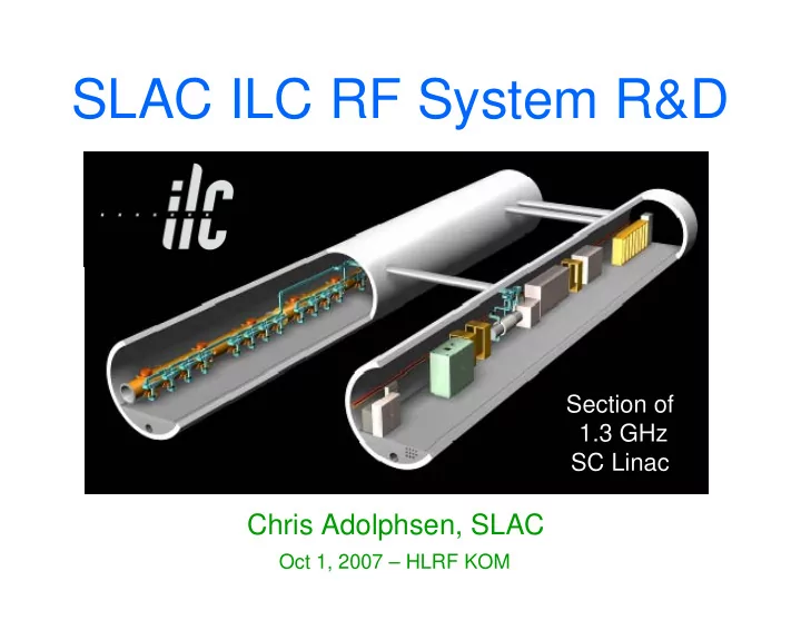
Chris Adolphsen, SLAC
Oct 1, 2007 – HLRF KOM
Section of 1.3 GHz SC Linac
SLAC ILC RF System R&D Section of 1.3 GHz SC Linac Chris - - PowerPoint PPT Presentation
SLAC ILC RF System R&D Section of 1.3 GHz SC Linac Chris Adolphsen, SLAC Oct 1, 2007 HLRF KOM ILC Main Linac RF Unit (1 of 560) RF System Gradient = 31.5 MV/m Rep Rate = 5 Hz Beam Current = 9.0 mA Cavity Power = 280 kW Cavity
Oct 1, 2007 – HLRF KOM
Section of 1.3 GHz SC Linac
(9-8-9 Cavities per Cryomodule)
Gradient = 31.5 MV/m Rep Rate = 5 Hz Beam Current = 9.0 mA Cavity Power = 280 kW Cavity Fill Time = 600 μs Bunch Train Length = 970 μs
A New Klystron Modulator for XFEL based on PSM Technology WEPMN073 Marx Bank Technology for the ILC THOBKI02 A High Voltage Hard Switch for the ILC WEPMN113 Converter-Modulator Design and Operations WEPMS028 High Power Switch for the SMTF Modulator WEPMS044 Developments of Long-pulse Klystron Modulator for the STF THIBKI04 Design and Status of the XFEL RF System TUXC03 RF Sources for the ILC THIBKI01
Klystrons Modulators
Grid-less IOT for Accelerator Applications WEPMS093 Klystron Development by TETD THIBKI03 Testing of 10 MW MBKs for the European X-ray FEL at DESY WEPMN013 Development and Testing of the ILC Marx Modulator TUOAC02
Second Order Ruled Surfaces in Design of Sheet Beam Guns THPAS063 Electron Gun and Cavity Designs for High Power Gridded Tube WEPMN054 WEPMN119
Klystrons (cont)
High-Power Ribbon-Beam Klystron High-Power Coupler Component Test Stand Status and Results WEPMS017 Compact Waveguide Distribution with Asymmetric Shunt Tees for the European XFEL MOPAN015 An RF Waveguide Distribution System for the ILC Test Accelerator at Fermilab’s NML WEPMS043 A Coaxial Coupling Scheme for the ILC SRF Cavity WEPMS049
Power Couplers RF Distribution
Multipacting Simulations of TTF-III Coupler Components WEPMS041 Construction of the Baseline SC Cavity System for STF at KEK WEPMN027 R&D Status of KEK High Gradient Cavity Package WEPMN032
IGCT’s
Capacitor Banks IGBT Redundant Switch Bouncer Choke
2 m
120 kV Output Cable Buck Regulator Coarse Vernier (3+ 1 Redundancy) 12 kV Cells (10+ 2 Redundancy) Fine Vernier
Develop alternative Marx approach to reduce the cost, size and weight of the modulator (no oil-filled transformers) and to improve its efficiency, reliability and manufacturability.
Produces 90 kV, 50A, 100 μsec Pulses
Advantage of Marx for ILC ... ... COMPACT !!! ... LOW COST !!!
ILC Modulator
120-150 kV, 120-150 A, 1.5 ms,
5 Hz Klystron Pulses
~ 750 Modulators Required
Use Marx topology to beat the
long pulse problem
Switch additional stages as
pulse droops, maintain flattop with affordable size capacitor bank
Minimize Overall Size and Cost
SBIR Goal
Design, build, deliver a fully
functioning first article for evaluation & tube testing
SWITCHING BOOST TRANS- FORMER HV RECTIFIER AND FILTER NETWORK ENERGY STORAGE
Other Alternative Modulators
DTI is building a 120 kV, 130 A IGBT Series Switch with a bouncer to be delivered to SLAC
Baseline: 10 MW Multi-Beam Klystrons (MBKs) with ~ 65% Efficiency: Being Developed by Three Tube Companies in Collaboration with DESY Thales (6 built) CPI (1) Toshiba (1)
750 hours, 80 % at full power
meets design goal
Nominal Power for 31.5 MV/m Operation at ILC 6-Beam Gun
Why Sheet Beam ?
current (at a given beam voltage) while still maintaining low current density for efficiency
lighter than other
eliminates power required for solenoid Designed to be MBK plug compatible with similar or better efficiency
The elliptical beam is focused in a periodic permanent magnet stack that is interspersed with rf cavities
Lead shielding Magnetically shielded from
Have done: 3D Gun simulations of a 130 A, 40:1 aspect ratio elliptical beam traversing 30 period structures. 3D PIC Code simulations
beam. Electron beam Permanent Magnet Cell RF cavity
Gun Current RF Cavities Magnetic Cells Cathode Temp
FY08.
beam transport simulations and allow a more rapid turnaround for electron gun changes.
parallel with little feedback from the beam tester. A rebuild of the klystron can incorporate design changes motivated by the beam tester.
Carbon beam probe assembly Gun and Beam Profile Monitor
Fixed Tap-offs Circulators Variable Tap-offs (VTOs) 3 dB Hybrids
RF Feeds
Length = 1.6 m Machined Aluminum, Dip-Brazed Rotatable Flanges
RF Input
Load Variable Tap-off Hybrid
3 dB Hybrid
SLAC is building VTOs and hybrids and acquiring parts to assemble rf distribution systems for FNAL CMs A VTO and hybrid have
ms, 5 Hz at atmospheric pressure
S11 = -39.3 dB S21 = -51.4 dB S31 = -0.034 dB S11 = -37.0 dB S21 = -0.030 dB S31 = -30.1 dB
1.26 1.28 1.3 1.32 1.34
VTO with ~0 Degrees Rotation
S11 S21 S31
S Parameter Amplitude (dB) Frequency (GHz)
1.26 1.28 1.3 1.32 1.34
VTO with ~45 Degrees Rotation
S11 S21 S31
S Parameter Amplitude (dB) Frequency (GHz)
1 2 3 4
Case Not Sorted [%] Sorted [%] Individual P’s and Q’s 0.0 0.0 (VTO and Circ) 1 P, individual Q’s 2.7 ± 0.4 2.7 ± 0.4 (Circ but no VTO) P’s in pairs, Q’s in pairs 7.2 ± 1.4 0.8 ± 0.2 (VTO but no Circ) 1 P, Q’s in pairs 8.8 ± 1.3 3.3 ± 0.5 (no VTO, no Circ) Gi set to lowest Glim 19.8 ± 2.0 19.8 ± 2.0 (no VTO, no Circ)
Optimized 1−〈G〉/〈Glim〉; results for 100 seeds
Consider uniform distribution of gradient limits (Glim)i from 22 to 34 MV/m in a 26 cavity rf unit - adjust cavity Q’s and/not cavity power (P) to maximize overall gradient while keeping gradient uniform (< 1e-3 rms) during bunch train
Input Power
Design complicated by need for tunablity (Qext), HV hold-off, dual vacuum windows and bellows for thermal expansion.
4 60 mm no no Tristan Disk KEK1 62 mm 62 mm 40 mm 40 mm Cold Coax Dia. 2 possible possible Disk LAL TW60 2 possible possible Cylindrical LAL TTF5 3 no no Capacitive Disk KEK2 62 yes yes Cylindrical TTF-3 # Fabricated Variable Qext Bias-able Cold Window
Orsay Facilities (shown below) - can process about 30
couplers / yr. Down to ~ 20 hours of rf processing time.
SLAC building similar assembly facilities to provide
FNAL with conditioned TTF-3 couplers.
Gowning Area SLAC Modifications Eliminate separate material pass-through More class 10 area Class 1000 => 100 Remote vacuum bake Class 100 Storage Lockers Class 10 Office Space Vacuum Oven – possible upgrade Air Handling System Air Shower Ramp – if raised floor
25 mm 38 mm Pump-Out Port Perturbed TM110 Mode Pillbox Cavity
Opens fully for cleaning compared to enclosed Orsay design, and does not use indium seals as in KEK split-WG design
RF In RF Out
RF load window window WG to coax DUT RF in
Facility assembled and operating – initially testing 600 mm long, 40 mm diameter stainless-steel and Cu-coated coaxial sections
Outer conductor wall of the Device Under Test (DUT) Threaded anchor side Slip-fit side to accommodate expansion
e-pickup PMT PMT Device Under Test
5 10 15 20 25 10 10
110
210
3uA Current of Ion pump 10C 10B 5 10 15 20 25 500 1000 1500 Power of klystron: kW Pulse W idth: us 5 10 15 20 25
E-pickup: V 5 10 15 20 25 30 500 1000 us Delayed time of the signal from e-pickup compared with RF pulse 5 10 15 20 25
1 mV Upstream PMT Downstream PMT
1.2MW@1.1ms 13hr
Second Processing of a 600 mm Long S/S Section
200 400 600 800 1000 1200 1400 50 100 150 Current of Ion Pume: uA Forward power: kW 200 400 600 800 1000 1200 1400
Electron signal:mV electron signal amplitude vacuum level
600mm long straight SS coax section test results 600mm long straight Copper plated SS coax section test results ILC TW Operating Point (280 kW)
Faya Wang
200 400 600 800 1000 1200 0.2 0.4 0.6 0.8 1 1.2 RF Input Power (kW) Average Delta third order fourth order fifth order sixth order seven order SS(1.3@310) Cu(1.3@410)
Faya Wang
time shortens in presence of magnetic field or high power spike).
disappearing for long periods.
RF Input Low Freq Probe Signal
Waveforms
(50 μs / division)
Harmonic (1.3 GHz) Content
Relative Amp -vs- Time (μs)
Produces 5 MW, 1.4 msec pulses at 5 Hz with a TH2104C klystron and a SNS-type modulator Source powers a coupler test stand and a normal-conducting ILC e+ capture cavity
Coupler Component Test Stand & Coupler Processing Capture Cavity RF Switch
Goal: Power with 5 MW, 1 msec pulses to produce 15 MV/m gradient
Water + Borax Flow Oil Non-Conducting Tubes HV Connection
HV Water Load
Each new test stand will have
Power Supply
HV Water Load Filament PS Transformer Klystron Socket
Will run independently, 24/7, with summary data archived for trends, detailed data for faults.
SLAC pursuing alternate designs while XFEL concentrating
more on baseline approaches.
Marx Modulator approach looks promising. First Toshiba 10 MW MBK successful, Thales tubes have
run tens of khour, design evolved to correct problems. Horizontal versions being developed.
A sheet beam klystron is being built that is more compact,
lighter and likely less expensive than the MBK.
Evaluating various rf distribution approaches to lower
system cost and maximize useable gradient.
US program ramping up, includes coupler development.