
SLIDE 1
Slides for Lecture 9
ENCM 501: Principles of Computer Architecture Winter 2014 Term Steve Norman, PhD, PEng
Electrical & Computer Engineering Schulich School of Engineering University of Calgary
6 February, 2014
ENCM 501 W14 Slides for Lecture 9
slide 2/23
Previous Lecture
◮ completion of DRAM coverage ◮ introduction to caches
ENCM 501 W14 Slides for Lecture 9
slide 3/23
Today’s Lecture
◮ continued coverage of cache design and cache
performance Related reading in Hennessy & Patterson: Sections B.1–B.3.
ENCM 501 W14 Slides for Lecture 9
slide 4/23
Review: Example computer with only one level of cache and no virtual memory
CORE DRAM CONTROLLER DRAM MODULES CACHE L1 I- CACHE L1 D-
We’re looking at this simple system because it helps us to think about cache design and performance issues while avoiding the complexity of real systems like the Intel i7 shown in textbook Figure 2.21.
ENCM 501 W14 Slides for Lecture 9
slide 5/23
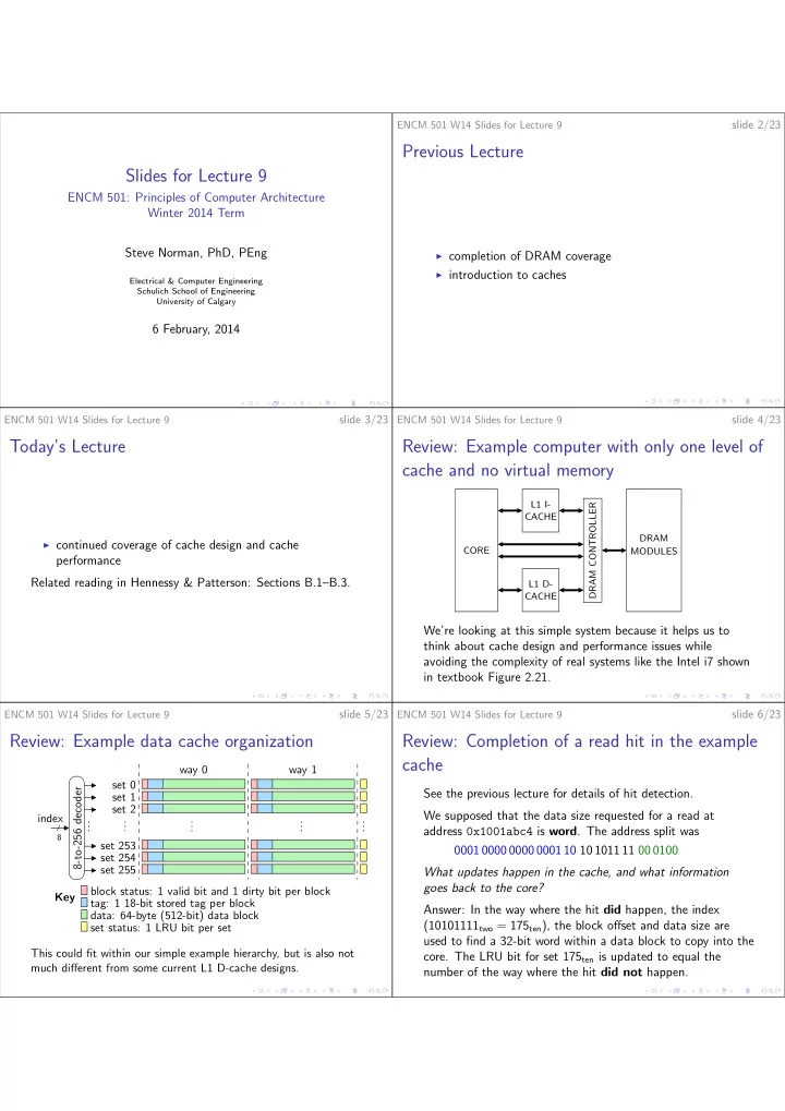
Review: Example data cache organization
. . . . . . . . . Key . . . . . . set 0 set 1 set 2 set 253 set 254 set 255 8-to-256 decoder
8
index block status: 1 valid bit and 1 dirty bit per block tag: 1 18-bit stored tag per block data: 64-byte (512-bit) data block set status: 1 LRU bit per set way 1 way 0 This could fit within our simple example hierarchy, but is also not much different from some current L1 D-cache designs.
ENCM 501 W14 Slides for Lecture 9
slide 6/23
Review: Completion of a read hit in the example cache
See the previous lecture for details of hit detection. We supposed that the data size requested for a read at address 0x1001abc4 is word. The address split was 0001 0000 0000 0001 10 10 1011 11 00 0100 What updates happen in the cache, and what information goes back to the core? Answer: In the way where the hit did happen, the index (10101111two = 175ten), the block offset and data size are used to find a 32-bit word within a data block to copy into the
- core. The LRU bit for set 175ten is updated to equal the