oldest oldest imaging imaging instruments instruments
play

Oldest Oldest Imaging Imaging Instruments Instruments circa - PDF document

Oldest Oldest Imaging Imaging Instruments Instruments circa 1000 CE 1600 CE Used to measure angles and positions A Brief History of Astronomical A Brief History of Astronomical Included No Optics Imaging


  1. Oldest “ Oldest “Imaging Imaging” ” Instruments Instruments • circa 1000 CE – 1600 CE • Used to measure angles and positions A Brief History of Astronomical A Brief History of Astronomical • Included No Optics Imaging Systems Imaging Systems – Astrolabe – Octant, Sextant – Tycho Brahe’s Mural Quadrant (1576) • Star Catalog accurate to 1' (1 arcminute = 1/60 ° ≈ limit of resolution of unaided human eye) – Astronomical Observatories were built by church as part of European Cathedrals • (possible subject for course term paper) 
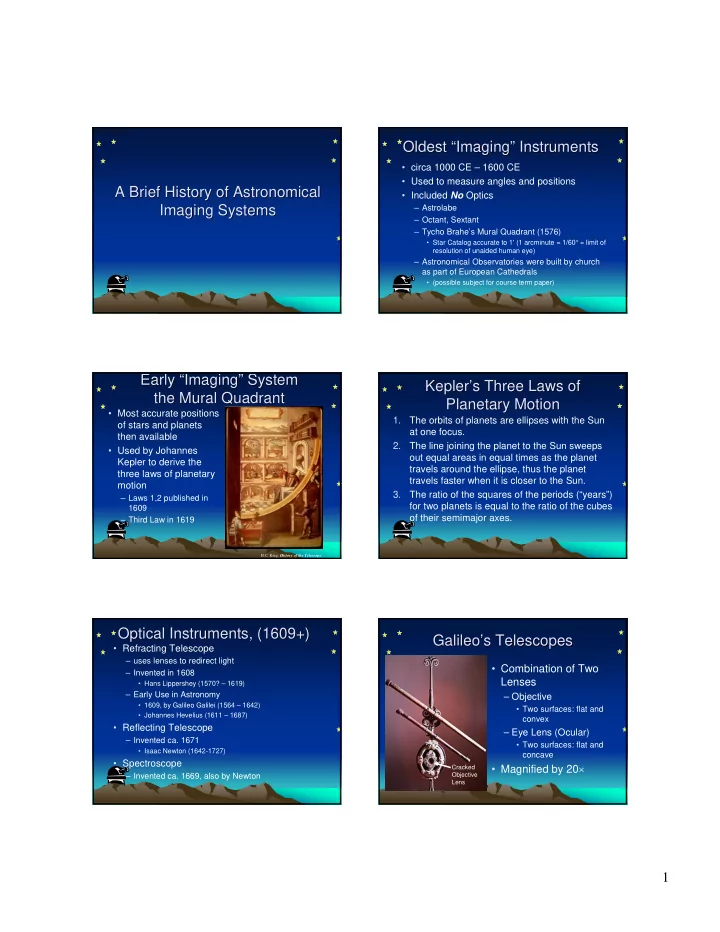
Early Early “ “Imaging Imaging” ” System System Kepler’ ’s s Three Laws of Three Laws of Kepler the Mural Quadrant the Mural Quadrant Planetary Motion Planetary Motion • Most accurate positions 1. The orbits of planets are ellipses with the Sun of stars and planets at one focus. then available 2. The line joining the planet to the Sun sweeps • Used by Johannes out equal areas in equal times as the planet Kepler to derive the travels around the ellipse, thus the planet three laws of planetary travels faster when it is closer to the Sun. motion 3. The ratio of the squares of the periods (“years”) – Laws 1,2 published in for two planets is equal to the ratio of the cubes 1609 of their semimajor axes. – Third Law in 1619 H.C. King, History of the Telescope Optical Instruments, (1609+) Optical Instruments, (1609+) Galileo’ Galileo ’s Telescopes s Telescopes • Refracting Telescope – uses lenses to redirect light • Combination of Two – Invented in 1608 Lenses • Hans Lippershey (1570? – 1619) – Early Use in Astronomy – Objective • 1609, by Galileo Galilei (1564 – 1642) • Two surfaces: flat and • Johannes Hevelius (1611 – 1687) convex • Reflecting Telescope – Eye Lens (Ocular) – Invented ca. 1671 • Two surfaces: flat and • Isaac Newton (1642-1727) concave • Spectroscope • Magnified by 20 × Cracked – Invented ca. 1669, also by Newton Objective Lens 1

  2. Galilean Telescope Galilean Telescope Galilean Telescope Galilean Telescope θ θ′ Ray entering at angle θ emerges at angle θ′ > θ f objective • Ray incident “above” the optical axis Larger ray angle ⇒ angular magnification emerges “above” the axis • image is “upright” • Small Field of View Keplerian Telescope Keplerian Telescope Keplerian Telescope Keplerian Telescope θ′ θ Ray entering at angle θ emerges at angle θ′ f objective f eyelens where | θ′ | > θ Ray incident “above” the optical axis Larger ray angle ⇒ angular magnification emerges “below” the axis image is “inverted” “ “Refractive Index Refractive Index” ” Sample Refractive Indices Sample Refractive Indices • Denoted by n • Vacuum: n = 1.0 • Measure of ratio of velocity of light in n ≈ 1.00003 ≈ 1.0 • Air: matter to that in vacuum n ≈ 1.33 • Water c n = 1.71 ≤ n ≤ 1.46 • Glass: v c = velocity in vacuum ≈ 3 × 10 8 meters/second v = velocity in medium measured in same units n ≥ 1.0 2

  3. Lenses Redirect (“ “Bend Bend” ”) Light ) Light Refracted Angles Determined Lenses Redirect ( Refracted Angles Determined by Refraction due to Different n by Refraction due to Different n by “ by “Snell Snell’ ’s Law s Law” ” θ = θ n sin n sin 1 1 2 2 Incident Ray L O M P θ 1 - θ 1 n Reflected Ray − ⇒ θ = θ 1 1 sin sin N Q n 1 2 1 n n 2 2 Refracted Ray θ 2 Problem with Refracting Problem with Refracting Optical Dispersion Optical Dispersion Telescopes: Telescopes: “ “Optical Dispersion Optical Dispersion” ” • Refractive index n of glass is not constant • n of glass tends to DECREASE with increasing wavelength λ • ⇒ Refracted angles change with wavelength λ • Focal length f of lens tends to INCREASE with n increasing wavelength λ – Different colors “focus” at different distances – “Chromatic Aberration” Ultraviolet Infrared λ Chromatic Aberration Chromatic Aberration Minimize Chromatic Aberration Minimize Chromatic Aberration • Chromatic aberration is less noticeable for lenses with long focal lengths f 3

  4. Later Methods to Diminish Later Methods to Diminish Hevelius’ ’ Refractor, ca. 1650 Refractor, ca. 1650 Hevelius Chromatic Aberration Chromatic Aberration Objective Lens • Create lens systems from multiple lenses made from different glasses – “doublets” or “triplets” – Designed so that chromatic aberrations “cancel” for some wavelengths Eye Lens • Difficult to design and fabricate • Beyond capability of early optical technicians H.C. King, History of the Telescope Easy Way to Eliminate Easy Way to Eliminate “Achromatic “ Achromatic” ” Lenses Lenses Chromatic Aberration Chromatic Aberration • “Achromatic” means • Don’t use lenses!! “no color” • Two (or more) lenses with different glasses – “Crown”, with smaller n – “Flint”, with larger n f All colors “focus” at same distance f Large Historical Reflecting Large Historical Reflecting Newton Newton’ ’s Reflector s Reflector Telescope Telescope • ca. 1671 • 1"-diameter mirror • no chromatic aberration – mirrors reflect all wavelengths at the same angle! Lord Rosse’s 1.8 m (6'-diameter) telescope metal mirror, 1845 H.C. King, History of the Telescope H.C. King, History of the Telescope 4

  5. History of Imaging Sensors History of Imaging Sensors History of Imaging Sensors History of Imaging Sensors • Eye • Groundbased Infrared Imaging – Limited sensitivity – 1856: using thermocouples and telescopes – Limited range of wavelengths (“one-pixel sensors”) – Images can be “stored” only “by hand” (drawings) – 1900+: IR measurements of planets • Image Recording Systems – 1960s: IR survey of sky (Mt. Wilson, lead sulfide − PbS − detector) – Chemical-based Photography • wet plates, 1850 + • Spacebased Infrared Imaging • dry plates, 1880+ – 1983: IRAS (Infrared Astronomical Satellite) • Kodak plates, 1900+ • cooled Silicon and Germanium detectors – Physics-based Photography, 1970 + – 1989: COBE (Cosmic Background Explorer) • Electronic Sensors, CCDs History of Imaging Sensors History of Imaging Sensors Galileo I (Convair Galileo I ( Convair 990) 990) • Started in 1965 • Airborne Infrared Observatories • Several “ports” available for cameras – Galileo I (Convair 990), 1965 – 4/12/1973 (crashed) • Crashed 4/12/1973 – Frank Low, 12"–diameter telescope on NASA – midair collision on landing at NAS Moffet Learjet, 1968 – Kuiper Airborne Observatory (KAO) (36"- diameter telescope) NASA Learjet, 1968 NASA Learjet, 1968 Kuiper Airborne Observatory Kuiper Airborne Observatory • 12"–diameter telescope, by Frank Low • Modified C-141 Starlifter • 2/1974 – 10/1995 • ceiling of 41,000' is above 99% of water vapor, which absorbs most infrared radiation 5

  6. Stratospheric Observatory for Stratospheric Observatory for Spaceborne Observatories Spaceborne Observatories Infrared Astronomy − − SOFIA SOFIA Infrared Astronomy • “Orbiting Astronomical Observatory” • Boeing 747SP (OAO), 1960s • 2.7-m Mirror (106") • “Infrared Astronomical Satellite” (IRAS), 1980s • Hubble Space Telescope (HST), 1990 • Chandra (Advanced X-ray Astrophysics Facility= AXAF), 7/1999 History of Imaging Systems for History of Imaging Systems for Jansky Radio Telescope Jansky Radio Telescope Radio Astronomy Radio Astronomy • Wavelengths λ are much longer than visible light – millimeters (and longer) vs. hundreds of nanometers • History – 1932: Karl Jansky (Bell Telephone Labs) investigated use of “short waves” for transatlantic telephone communication – 1950s: Plans for 600-foot “Dish” in Sugar Grove, WV (for receiving Russian telemetry reflected from Moon) – 1960s 305m Dish at Arecibo, Puerto Rico – 1963: Penzias and Wilson (Bell Telephone Labs), “Cosmic Microwave Background” 1932 – 1980: “Very Large Array” (= VLA) in New Mexico Image courtesy of NRAO/AUI Very Large Array = VLA Very Large Array = VLA Large Radio Telescopes Large Radio Telescopes • 27 telescopes 100m at Green Bank, WV • 25m diameter • transportable on rails • separations up to 36 km (22 miles) 305m at Arecibo, Puerto Rico Image courtesy of NRAO/AUI Image courtesy of NRAO/AUI http://www.naic.edu/about/ao/telefact.htm 6

Download Presentation
Download Policy: The content available on the website is offered to you 'AS IS' for your personal information and use only. It cannot be commercialized, licensed, or distributed on other websites without prior consent from the author. To download a presentation, simply click this link. If you encounter any difficulties during the download process, it's possible that the publisher has removed the file from their server.

Recommend


More recommend