
SLIDE 1
Multicycles Exception Between Two Synchronous Clock Domains
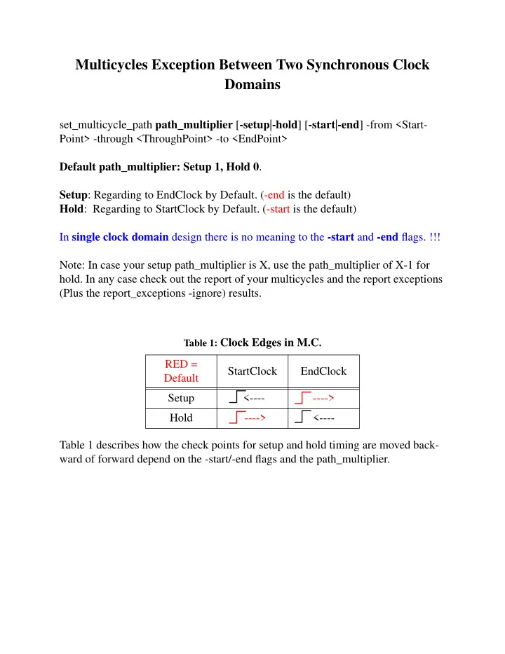
set_multicycle_path path_multiplier [-setup|-hold] [-start|-end] -from <Start- Point> -through <ThroughPoint> -to <EndPoint> Default path_multiplier: Setup 1, Hold 0. Setup: Regarding to EndClock by Default. (-end is the default) Hold: Regarding to StartClock by Default. (-start is the default) In single clock domain design there is no meaning to the -start and -end flags. !!! Note: In case your setup path_multiplier is X, use the path_multiplier of X-1 for
- hold. In any case check out the report of your multicycles and the report exceptions
(Plus the report_exceptions -ignore) results. Table 1 describes how the check points for setup and hold timing are moved back- ward of forward depend on the -start/-end flags and the path_multiplier.
Table 1: Clock Edges in M.C.
RED = Default StartClock EndClock Setup <----
- --->
Hold
- --->