Serial Communication Asynchronous communication Synchronous - - PDF document

serial communication
SMART_READER_LITE
LIVE PREVIEW

Serial Communication Asynchronous communication Synchronous - - PDF document

Serial Communication Asynchronous communication Synchronous communication clock TX RX data A->B Device A Device B Device A Device B data B->A RX TX asynchronous no clock Synchronous with clock Data represented by setting


slide-1
SLIDE 1

Serial Communication

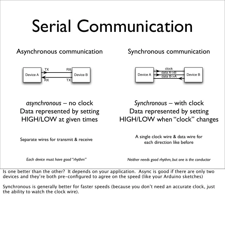
Separate wires for transmit & receive

Asynchronous communication asynchronous – no clock Data represented by setting HIGH/LOW at given times Synchronous communication Synchronous – with clock Data represented by setting HIGH/LOW when “clock” changes

A single clock wire & data wire for each direction like before

Device A Device B TX RX RX TX Device A Device B clock data A->B data B->A

Each device must have good “rhythm” Neither needs good rhythm, but one is the conductor

Is one better than the other? It depends on your application. Async is good if there are only two devices and they’re both pre-configured to agree on the speed (like your Arduino sketches) Synchronous is generally better for faster speeds (because you don’t need an accurate clock, just the ability to watch the clock wire).

slide-2
SLIDE 2

I2C, aka “T wo-wire”

Master device

Peripheral device 1 Peripheral device 2 Peripheral device N

  • • •

data

SDA

clock

SCK

Synchronous serial bus with shared a data line

  • Up to 127 devices on one bus
  • Up to 1Mbps data rate
  • Really simple protocol (compared to USB,Ethernet,etc)
  • Most microcontrollers have it built-in

a little network for your gadgets

The shared data line means the devices have to agree on when they should “talk” on it. Like how on CBs you say “over” and “over & out” to indicate you’re finished so the other person talk. See “Introduction to I2C”: http://www.embedded.com/story/OEG20010718S0073 “I2C” stands for “Inter-Integrated Circuit”, but no one calls it that And if your microcontroller doesn’t have I2C hardware built-in, you can fake it by hand in software (for master devices anyway)

slide-3
SLIDE 3

Many I2C devices

touch sensor compass fm transmitter non-volatile memory LCD display temperature & humidity sensor And many others

(gyros,keyboards, motors,...)

Images from Sparkfun.com,except LCD from matrixorbital.com

slide-4
SLIDE 4

Obligatory BlinkM Promo

I2C Smart LED

Does all the hard PWM & waveform generation for you

You should be able to buy these from Sparkfun.com in a month or so.

slide-5
SLIDE 5

Nintendo Wii Nunchuck

  • Standard I2C interface
  • 3-axis accelerometer with

10-bit accuracy

  • 2-axis analog joystick with

8-bit A/D converter

  • 2 buttons
  • $20

If you look at the architecture for the Nintendo Wii and its peripherals, you see an almost un-Nintendo adherence to standards. The Wii controllers are the most obvioius examples of this. The Wii controller bus is standard I2C. The Wii remote speaks Bluetooth HID to the Wii (or your Mac or PC) Because it uses standard I2C, it’s easy to make the Nunchuck work with Arduino, Basic Stamp or most other microcontrollers. See: http://www.wiili.org/index.php/Wiimote/Extension_Controllers/Nunchuk and: http://www.windmeadow.com/node/42 and: http://todbot.com/blog/2007/10/25/boarduino-wii-nunchuck-servo/ And then there’s the Wii Remote, besides Bluetooth HID, it also has accelerometers, buttons, speaker, memory, and is I2C master.

slide-6
SLIDE 6

Accelerometer?

  • Measures acceleration

(changes in speed)

  • Like when the car

pushes you into the seat

  • Gravity is acceleration
  • So, also measures tilt

horizontal tilt right tilt left

slide-7
SLIDE 7

Nunchuck Accelerometer

X Z Y

Wii Remote & Nunchuck accelerometer axes

I’m not sure if I have the Nunchuck one right. Wiimote axis image from http://www.wiili.org/index.php/Wiimote

slide-8
SLIDE 8

I2C on Arduino

  • I2C built-in on Arduino’s

ATmega168 chip

  • Use “Wire” library to access it
  • Analog In 4 is SDA signal
  • Analog In 5 is SCK signal

SDA SCK

slide-9
SLIDE 9

Arduino “Wire” library

Writing Data

Start sending Join I2C bus

(as master)

Send data Load Wire library Stop sending

And what the various commands do are documented in the instructions / datasheet for a particular device.

slide-10
SLIDE 10

Arduino “Wire” library

Reading Data

Request data from device Join I2C bus

(as master)

Get data

What kinds of interactions you can have depends on the device you’re talking to Most devices have several “commands”

And what the various commands do are documented in the instructions / datasheet for a particular device.

slide-11
SLIDE 11

Wiring up the Nunchuck

We could hack off the connector and use the wires directly But instead let’s use this little adapter board

slide-12
SLIDE 12

Wii Nunchuck Adapter

SCK GND +V SDA n/c n/c

Nunchuck Pinout

(looking into Nunchuck connector)

Adapter Pinout

+V SCK SDA GND

Note there *are* labels on the adapter, but they’re wrong. So you’ll have to trust the diagrams above

slide-13
SLIDE 13

Wiring it Up

GND SDA +5V SCK SDA (pin 4) SCK (pin5)

slide-14
SLIDE 14

Pluggin’ in the ‘chuck

slide-15
SLIDE 15

Trying the Nunchuck

“NunchuckPrint”

Read the Nunchuck every 1/10th of a second & print out all the data:

  • joystick position (x,y)
  • accelerometer (x,y,z)
  • buttons Z,C

X

Z

Y Uses the beginnings of an Arduino library I’m writing.

slide-16
SLIDE 16

Adding a Servo

Move the servo by moving your arm “NunchuckServo” You’re a cyborg!

Also press the Z button to flash the pin 13 LED

Utilizes the task slicing mentioned before

slide-17
SLIDE 17

Nunchuck Servo

Twist the nunchuck and the servo matches your movement

slide-18
SLIDE 18

Segway Emulator

Same basic code as NunchuckServo. For details see: http://todbot.com/blog/2007/10/25/boarduino-wii-nunchuck-servo/

slide-19
SLIDE 19

Going Further

  • Servos
  • Hook several together to create a multi-

axis robot arm

  • Make a “servo recorder” to records your

arm movements to servo positions and plays them back

  • Great for holiday animatronics
slide-20
SLIDE 20

Going Further

  • I2C devices
  • Try out some other devices
  • Just string them on the same two wires used

for the Nunchuck

  • Cooperative Multitasking
  • Try making a theremin with nunchuck & piezo
  • See if previous examples can be made more

responsive

slide-21
SLIDE 21

Going Further

  • Nunchuck
  • It’s a freespace motion sensor. Control

anything like you’re waving a magic wand!

  • What about the joystick? We didn’t even

get a chance to play with that

  • Alternative input device to your

computer: control Processing, etc.

slide-22
SLIDE 22

Summary

You’ve learned many different physical building blocks LEDs switches/buttons resistive sensors motors piezos servos

X

Z

Y

accelerometers

slide-23
SLIDE 23

Summary

And you’ve learned many software building blocks pulse width modulation serial communication digital I/O analog I/O data driven code frequency modulation multiple tasks I2C

slide-24
SLIDE 24

Summary

Hope you had fun and continue playing with Arduino Feel free to contact me to chat about this stuff

slide-25
SLIDE 25

Tod E. Kurt

tod@todbot.com

END Class 4

http://todbot.com/blog/bionicarduino/

Feel free to email me if you have any questions.