
SLIDE 1
1
Serial Communications
2
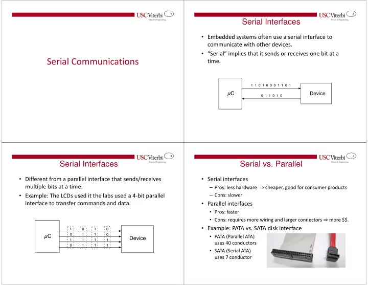
Serial Interfaces
- Embedded systems often use a serial interface to
communicate with other devices.
- “Serial” implies that it sends or receives one bit at a
time.
3
Serial Interfaces
- Different from a parallel interface that sends/receives
multiple bits at a time.
- Example: The LCDs used it the labs used a 4-bit parallel
interface to transfer commands and data.
4
Serial vs. Parallel
- Serial interfaces
– Pros: less hardware ⇒ cheaper, good for consumer products – Cons: slower
- Parallel interfaces
- Pros: faster
- Cons: requires more wiring and larger connectors ⇒ more $$.
- Example: PATA vs. SATA disk interface
- PATA (Parallel ATA)
uses 40 conductors
- SATA (Serial ATA)