
SLIDE 1
Modeling Wind Shielding for FPSO Tandem Offloading using CFD Bob - - PowerPoint PPT Presentation
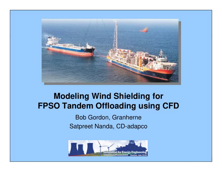
Modeling Wind Shielding for FPSO Tandem Offloading using CFD Bob Gordon, Granherne Satpreet Nanda, CD-adapco Presentation Outline FPSO Tandem Offloading Examples of Shielding in Offshore Applications Wind Tunnel Tests for Tandem
2
3
4
5
6
7
8
9
10
11
12
13
14
15
16
17
18
Tandem Arrangement (450 m separation) Shuttle Tanker Only Wind Tunnel Measurement OCIMF
19
20