leg legal Ad l Address: ess: ENGINEERING 24122 Bergamo, Via - - PDF document

leg legal ad l address ess engineering 24122 bergamo via
SMART_READER_LITE
LIVE PREVIEW

leg legal Ad l Address: ess: ENGINEERING 24122 Bergamo, Via - - PDF document

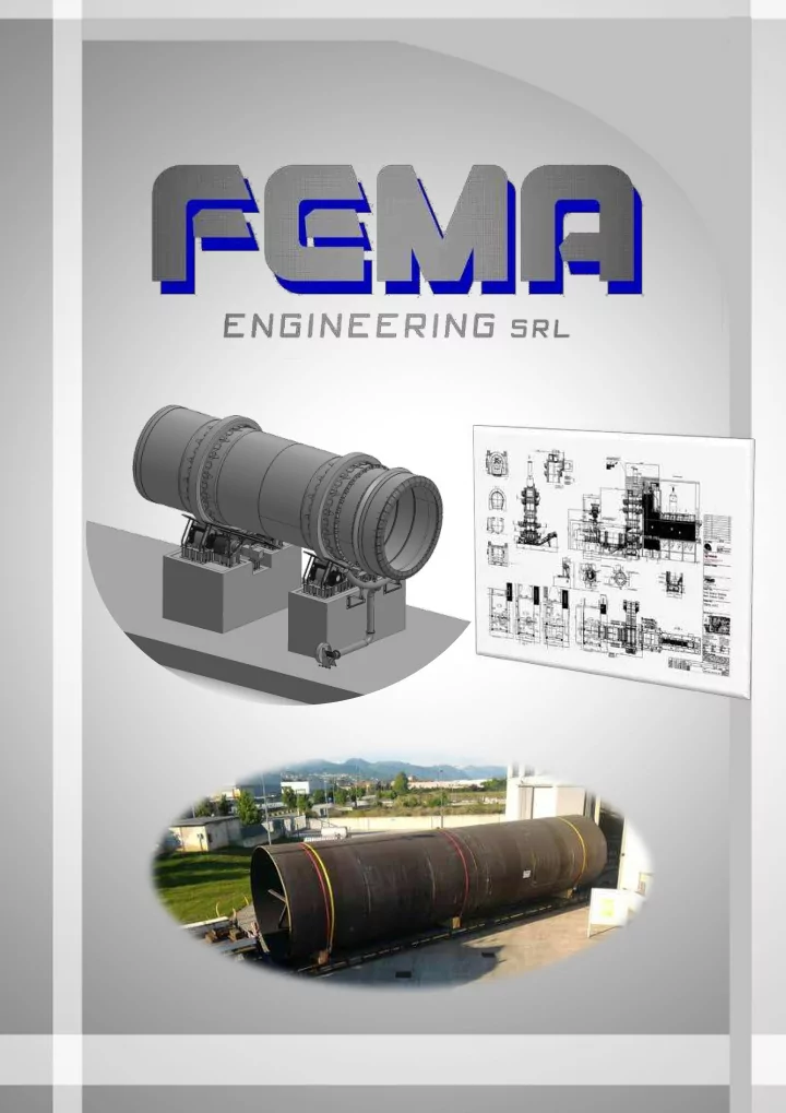
leg legal Ad l Address: ess: ENGINEERING 24122 Bergamo, Via Tiraboschi 48 MECHANICAL CONSTRUCTIONS Mail il Addr Addres ess: Commercial Dept - & MEDIUM-HEAVY STEEL STRUCTURES com@femaeng.net www.femaengineering.it To all


slide-1
SLIDE 1
slide-2
SLIDE 2

ENGINEERING MECHANICAL CONSTRUCTIONS & MEDIUM-HEAVY STEEL STRUCTURES

legal Address: 24122 Bergamo, Via Tiraboschi 48 p.iva/ cod. fis. 04071080164 – REA (BG) 432650

leg legal Ad l Address: ess: 24122 Bergamo, Via Tiraboschi 48 Mail il Addr Addres ess: Commercial Dept - com@femaeng.net www.femaengineering.it

  • Pag. 1

To all Customers Bergamo, 15th May 2015 With the present communication we transmit You the data of the updated Company’s profile: Company’ name : FEMA ENGINEERING srl Legal Address (Street/House number) : Via Tiraboschi, nr. 48 Postal Code/City : 24122 Bergamo (BG) ‐ ITALY Country : IT P.IVA /C.F. : 04071080164 Mail Address :  General Manager dir@femaeng.net  Commercial Dept. com@femaeng.net  Technical Dept. tech@femaeng.net  Administration Dept. admin@femaeng.net  Purchasing Dept. procurement@femaeng.net We remain at your disposal for any further information, thanking you for the attention reserved to us we send our best regards.

slide-3
SLIDE 3

EN VI N VIRON M N MEN T N T PROTECTION N PLANT NTS

FEMA, as a company environment-friendly, manufactures plants for:

  • Incineration and recycle energetic power using waste;
  • Metal recycling process.

In c n cin e n er at io n a n an d n d r r ec ycl e l e en en er er get et ic po po wer er p pl an t s

The scope of work or these plants is the incineration of:

  • Municipal waste
  • Solid and liquid waste
  • Hospital waste
  • Toxic waste

Pl an t s t s f o f o r m r met a t al r e r ec ycl in g p pr o r o ces s

FEMA manufactures sm elting furnaces for the waste of:

  • Copper
  • Aluminium
  • Brass

Exam ple : I ncineration Plant w ith Rotary Kiln ∅ 4 ,7 x 1 4 m Exam ple : I ncineration Plant w ith Rotary Kiln ∅ 3 ,5 x 1 5 m

slide-4
SLIDE 4

Ther moval al or iZ A Tion P Pl an ant - Sin inga gapor e: F Load ad ing Gr Gr oup up – Char gin ging S g Syst em F Rot ar ar y K Kil n f f or

A Z A Rd ous W

us Wast ast es – Ø 4 4 ,0 x 0 x 1 2 1 2 ,0 ,0 m m F Loa

  • ad / U

/ Unl oa

  • ad s

seal s

  • “ f ema

ma d d r agg ggin ing s g seal ” F Secon

  • nd ar y Com

ComB ust ion

  • n Ch

ChamB er F We Wet A Ahs C Convey veyor

slide-5
SLIDE 5

Inci ncine ner at ion Pl n Pl ant nt - UK UK F Rot ar ar y K Kil n f f or

A Z A Rd ous W

us Wast ast es s – Ø 4 Ø 4 ,8 5 x 8 5 x 1 3 1 3 ,0 ,0 m m F Load ad / / U Unl oad ad se seal s s - “ f ema ma d d r agg ggin ing s g seal ” F t r t r an ansp spor t F inst st al al l at i t ion

slide-6
SLIDE 6

ROTAR ARY KI KILN S N S

FEMA is in the market as main supplier for the construction of the main machines of Cem ent Plants where the KI LN, designed and constructed directly in its workshop is the m ost important machine of the process. Thanks to effective partnership with companies leader in the cement field, the technical solutions are studied taking into consideration the production, technological and logistic requirem ents of the desired plant. Both the process and the machines are completely oriented on the customers’ needs Technological / constructive Characteristics:

  • Forged riding rings and rollers
  • Roundness tolerance for the kiln sections < 0,2
  • Blade seal or with pneumatic control
  • Thrust roller complete of hydraulic unit
  • Driving group through gear crown / pinion
  • As alternative driving group with rollers (without crown / pinion)

Solutions for Control and Maintenance

  • Application of pads easy to replace under the riding rings
  • Central and programmable lubrication system
  • Therm ocam era to measure and survey the tem peratures on the Shell
slide-7
SLIDE 7

TUBU BULAR AR M MILLS

FEMA’s tubular mills, designed for both wet and dry process, have adequate dimensions and characteristics to satisfy the clients’ needs and they have an installed power from 50 kW to 5.000 kW. According to their typology they can be divided as follows: ˜ Mill with heads on supports with bearing in white m etal; ˜ Mills with shell supported by sliding pads; ˜ With or without drying chamber; ˜ With one or m ore grinding chambers; ˜ With Drive to be realized according to the requested power (with crown gear-pinion, with crown gear and double pinion, with central drive)

Co n s t r u t r uct i t io n F Feat u t ur e r es

  • Mill Shell:
  • With internal or external flanges to fix the heads
  • With machined bands for the sliding on the supports
  • Heads (for traditional m ills, without sliding pads):
  • One bloc in cast steel GS 20Mn5;
  • In composed execution, with neck in forged steel
  • Sliding pads, easy to adjust through an oleo-dynamic system
  • Crown gear in composed electrowelded execution, according to the most updated

technology, with toothed band in forged steel Cr Mo

Sl i l idin g n g P Pads Wh Wh it e Me Met al B Bear ar in g Gh Gh ir t Ge Gear

slide-8
SLIDE 8

AI AIR S S EPAR ARAT ATOR – FE FEMA

The Air Separator of third generation is a high efficiency machine realized according to internal engineering. The Separator is manufactured in various sizes in

  • rder to choose the best dimensioning for the different process values (capacity,

fineness, etc).

Air Separator - FM 3 0 0 Air Separator - FM 0 7 5

Construction Features

The separator is composed by:

  • Upper conical cylinder Casing, provided with a spiral tangential conduct for inlet of

classification air;

  • Fixed Guide Blades, adjustable for a correct air conveying;
  • Feeding System by m eans of two mouths;
  • Set of air tight rings placed between the fixed and the rotary parts;
  • Rotary Part dynamically balanced;
  • Drive Unit by means of motor and reducer or pulleys and transmission belts
  • Wear proof lining on all surfaces requiring such a protection

Technological Features

The feeding material, fed from the top through the two mouths, falls on the distribution ring to undergo centrifugation. It then reaches the classification area to m eet the air coming from the spiral tangential conduct. Under the action of gravity, centrifugal force, and the air entrainment force, the various particles are selected according to the single weights and dimensions. The fine material is carried by the air current through the bars of the classification cage and then conveyed into the upper central piping to be gathered into the external cyclones or directly into the bag filter. All the required fineness grades can be easily obtained by changing the speed of the classification cage (operating on the inverter in the Control Room). The bigger particles, not carried by the air through the classification cage, fall into the lower cone and are fed back to the mill.

slide-9
SLIDE 9

MECH CH AN AN ICAL CAL CO CON ST N STRUCT CTION

Engineering and Construction of big plants components, produced with certification on both materials and process : ˜ Bending and gauging of various types of steel plates; ˜ Machining and erection works; ˜ Welding according to EN procedure; ˜ Heat treatments; ˜ Sandblasting and painting of the surfaces.

Cr us h us h er Sh Sh af t Ridin g n g R Ro l l e l l er s Bus h in h in gs H o t

  • t G

Gas G Gen en er er at o r

  • r (Mech an i

n ical D l Des ign n / / Th er er mal P Pr o c

  • ces s )
slide-10
SLIDE 10

Ro t ar y C Co o l

  • o l er

er (Mech a h an ic ical D Des ig ign / / Th er er mal P Pr o c

  • ces

es s ) Rec ecei eivin g H H o p

  • pper

er p po s

  • s it io n
  • n ed

ed o n

  • n L

Lo ad ad C Cel l s l l s Lo ad ad/Un Un l o ad ad Leaf Seal al s f o f o r Ro Ro t ar y y Kil n (Me Mech an an ical al Des ign gn /Co n s t r t r uct i t io n/ In s n s t al l a l at i t io n )