
SLIDE 1
Lecture 22
Logistics
HW8 due Monday (6/2), HW9 due Friday (6/6) Ant extra credit due 6/6 Ant extra credit due 6/6 Take home extra credit final handed out 6/6 Final exam 6/9 8:30am Review?
Last lecture
Simplification
T d
1
CSE370, Lecture 24
Today
State encoding
One-hot encoding Output encoding
22
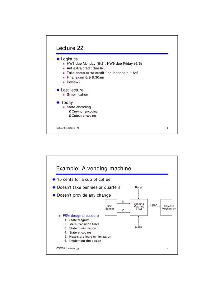
Example: A vending machine
15 cents for a cup of coffee Doesn’t take pennies or quarters
Reset
Doesn t take pennies or quarters Doesn’t provide any change
FSM-design procedure
- 1. State diagram
Vending Machine FSM N D Open Coin Sensor Release Mechanism
2
CSE370, Lecture 24
g
- 2. state-transition table
- 3. State minimization
- 4. State encoding
- 5. Next-state logic minimization
- 6. Implement the design
22
Clock