SLIDE 1 lecture 18
- ray tracing
- environment mapping
- refraction
for each pixel (x,y) { cast a ray through that pixel into the scene, and find the closest surface along the ray through that pixel compute the RGB value, based on that surface }
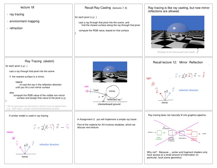
Recall Ray Casting (lectures 7, 8) Ray tracing is like ray casting, but now mirror reflections are allowed.
Shadow to be discussed next week. for each pixel (x,y) { cast a ray through that pixel into the scene if the nearest surface is a mirror, repeat re-cast the ray in the reflection direction until you hit a non-mirror surface else compute the RGB value of the visible non-mirror surface and assign that value to the pixel (x,y) } // All the techniques we discussed in lecture 8 can be applied here.
e.g. BSP trees, octrees, hierarchical bounding volumes
Ray Tracing (sketch)
mirror eye "reflected ray " "cast checkerboard ground
Recall lecture 12: Mirror Reflection
mirror light reflection direction mirror viewer reflection direction A similar model is used in ray tracing. In Assignment 3, you will implement a simple ray tracer. Part of the material for A3 involves shadows, which we discuss next lecture.
"primitive assembly" & clipping vertex processor clip coordinates rasterization fragment processor fragments pixels vertices
Ray tracing does not naturally fit into graphics pipeline. Why not? Because ....vertex and fragment shaders only have access to a small amount of information (in particular, local scene geometry)
SLIDE 2
Environment Mapping
If you want real time graphics with mirror surfaces, use "environment mapping" instead. An "environment map" is a "360 deg" RGB image of a scene, defined on the unit sphere centered at some scene point. We denote it E(rx, ry, rz) where r is direction of rays to the environment as seen from the scene point. E(rx, ry, rz)
physical situation
for each pixel (xp,yp) { cast a ray through (xp, yp) to the nearest scene point (x,y,z) if (x,y,z) has mirror reflectance { compute mirror reflection direction (rx, ry, rz) // copy environment map value I(xp, yp) = E(rx, ry, rz) } else compute RGB using Blinn-Phong (or other model) }
How does this differ from ray tracing ?
Environment Mapping Algorithm Example (Blinn and Newell 1976)
Notice reflections of windows in the teapot.
hand drawn (cylindrical) environment by Jim Blinn
This teapot has diffuse shading + mirror components. Today we will talk only about the mirror component. A more complex environment...
Cube map (Green 1986)
a data structure for environment maps Construct 6 images, each with 90 deg field of view angle.
Examples
google "cube map images"
These (cube mapped) environment maps are pre-computed. They are OpenGL textures.
How to index into a cube map? (derivation over next few slides)
Given reflection vector r = (rx, ry, rz), lookup E(rx, ry, rz) How ?
A:
Project r onto cube face. ( rx, ry, rz ) = ( rx, ry, rz ) / max { | rx | , | ry | , | rz | }. One of the components will have value +- 1, and this tells us which face of the cube to use. The other two components are used for indexing into that face. Need to remap the indices from [-1, 1] to [0, N) where each face of the cube map has NxN pixels.
Sphere Map
a second data structure for environment maps The reflection of the scene in a small mirror sphere.
SLIDE 3 Q: How much of scene is visible in the reflection off a mirror sphere ? A: - 180 degrees ? (half of the scene)
- between 180 and 360 degrees ?
- 360 degrees ?
(the entire scene) Claim: if you are given the reflection of a scene in a small spherical mirror, then you can compute what any mirror
- bject looks like (if know the object's shape).
Why? All you need to know is the reflection direction at each pixel and then use it to index index into the environment map defined by the given image of the sphere.
How to index into a sphere map?
Given reflection vector r = (rx, ry, rz), lookup E(rx, ry, rz) Q: How ? A: Map r = (rx, ry, rz) to (s, t) which is defined below. For a point on a unit sphere, Let's now derive the mapping. First observe:
Texture coordinates for a sphere map
Identify (s,t) coordinates with (nx, ny). To map r = (rx, ry, rz) to (s,t), assume orthographic projection, namely assume v = (0, 0, 1) for all surface points. Substituting for v and n and manipulating gives: (details in lecture notes)
early 1980s http://www.pauldebevec.com/ReflectionMapping/
Capturing Environment Maps with Photography
SLIDE 4 Hollywood: Terminator 2 (1991)
How was this achieved? Q: What implicit assumptions are we making when using environment maps ? A: We assume the environment is the same for all scene points (x,y,z). This essentially assumes that the environment is at infinity. Why is that wrong? Why does it not matter ? Q: For the scene below, which of the objects (1, 2, 3, 4) would be visible or partly visible either directly or in the mirror, if we used:
- ray tracing
- environment mapping
Q: For the scene below, which of the objects (1, 2, 3, 4) would be visible or partly visible directly, if we used:
- ray tracing
- environment mapping
A: 3, 4 (but not 1, 2) Q: For the scene below, which of the objects (1, 2, 3, 4) would be visible or partly visible in the mirror, if we used:
- ray tracing
- environment mapping
A: 2, 3, 4 (but not 1) Q: For the scene below, which of the objects (1, 2, 3, 4) would be visible or partly visible in the mirror, if we used:
- ray tracing
- environment mapping
A: 1, 3, 4 (but not 2)
SLIDE 5 Notice the poor resolution at the rim
"primitive assembly" & clipping vertex processor clip coordinates rasterization fragment processor fragments pixels vertices
Where do various steps of environment mapping occur in the graphics pipeline? Vertex processor ... ? Rasterizer .... ? Fragment processor ... ? Vertex processor computes the reflection vector r for each vertex, and looks up RGB values from environment map. Rasterizer interpolates RGB values and assigns them to the fragments. Fragment processor does basically nothing.
Solution 1 (bad, not used):
Why is this bad ? (Hint: think of what would happen for a square mirror. It would smoothly interpolate between the values at the four
- corners. That's not what real mirrors do.)
Vertex processor computes the reflection vector r for each vertex. Rasterizer interpolates reflection vectors and assigns them to the fragments. Fragment processor uses reflection vectors to look up RGB values in the environment map.
Solution 2 (good): Any image of a sphere can be used as an environment map. lecture 18
- ray tracing
- environment mapping
- refraction
Refraction
You can use environment mapping or ray tracing to get the RGB value. Environment mapping can be done in OpenGL 2.x and beyond using shaders.
SLIDE 6
See nice video here. http://3dgep.com/environment-mapping-with-cg-and-opengl/ #The_Refraction_Shader
Geri's Game (1997, Pixar, won Oscar for animation)
https://www.youtube.com/watch?v=9IYRC7g2ICg
Check out refraction in glasses around 2 minutes in. This was done using environment mapping.