
SLIDE 1
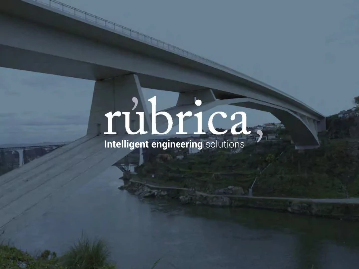
Intelligent engineering solutions Rbrica, the company Polonia - - PowerPoint PPT Presentation
Intelligent engineering solutions Rbrica, the company Polonia Polan umana Espaa omania Spain EE.UU talia Portugal USA al Marruecos China Morocco Mxico Colombia nia Mexico Panam Panama
EE.UU USA México Mexico Colombia Perú Peru Chile Uruguay Brasil Brazil Panamá Panama Paraguay Marruecos Morocco Portugal España Spain talia al nia China Polonia Polan umana
Arch Bridges Progressive Cantilevers Big Trusses Bridges Cable-stayed Bridges Side Cantilevers
Self-launching Truss Upstream Shoulders Underwater Concrete Floating Formwork Capping Beams Single-arm Grippers Precasts Grab Bucket Cut-and-cover tunnels Pavements Galleries Bored tunnels Junctions and niches Inverted Vaults
Rúbrica Engineering supplies special formwork in situ for bridges, wing travelers, precast molds, self-launching falsework, tunnel forms, and special systems for underground works and unique projects. Over 25 years of experience and more than 500 completed works.
OVERVIEW
L OR CROWN WAVEWALL
BRIDGE CONSTRUCTION METHODS - EQUIPMENT
IN SITU CONCRETING BRIDGES Variable depth Constant depth Cable stayed bridges Special projects Wing travellers Precast moulds LIFTING STRUCTURES
www.rubricabridges.com
This construction method is used for in-situ concreting of bridges or viaducts with consider a- ble spans. Equipment is positioned at the top of the pier ,
directions bi-laterally, constructing consecutive segments which form a T shaped, symmetrical
systems range between 3.5 and 5 metres. This allows reinforcement to be installed easily and safely. Equipment comprises the main structure, transfer rails, bed or base panel, e xternal and internal formwork and working platforms. T
segment, concrete is poured into the section made up of the e xternal and internal formwork and the bed. These panels are attached to the frontsection of the main structure and at the rear to theprevious segment. The form tr aveller is ad- vanced to the ne xt section by hydraulically sliding the entire assembly in transfer configu ation on the rails. Equipment for cantilever bridges is able to counteract bridge gradients and section cambers.
2.1 DESCRIPTION OF THE FORMWORK
www.rubricabridges.com
This construction method is used for in-situ concreting of bridges or viaducts with consider a- ble spans. Equipment is positioned at the top of the pier ,
directions bi-laterally, constructing consecutive segments which form a T shaped, symmetrical
systems range between 3.5 and 5 metres. This allows reinforcement to be installed easily and safely. Equipment comprises the main structure, transfer rails, bed or base panel, e xternal and internal formwork and working platforms. T
segment, concrete is poured into the section made up of the e xternal and internal formwork and the bed. These panels are attached to the frontsection of the main structure and at the rear to theprevious segment. The form tr aveller is ad- vanced to the ne xt section by hydraulically sliding the entire assembly in transfer configu ation on the rails. Equipment for cantilever bridges is able to counteract bridge gradients and section cambers.
This construction method is used for in-situ concreting of bridges or viaducts with considera-ble spans. Equipment is positioned at the top of the pier, or segment 0, and is advanced in opposite directions bi-laterally, constructing consecutive segments which form a T shaped, symmetrical
reinforcement to be installed easily and safely. Equipment comprises the main structure, transfer rails, bed or base panel, external and internal formwork and working platforms. To cast the segment, concrete is poured into the section made up of the external and internal formwork and the bed. These panels are attached to the frontsection of the main structure and at the rear to theprevious segment. The form traveller is ad-vanced to the next section by hydraulically sliding the entire assembly in transfer configuration on the rails. Equipment for cantilever bridges is able to counteract bridge gradients and section cambers.
2.1 DESCRIPTION OF THE FORMWORK
BALANCED CANTILEVER METHOD
Mersey Gateway bridge (Liverpool - UK) 6 no. R-1900 series form travellers for the construction of a cable stay bridge
Mersey Gateway bridge (Liverpool - UK) 6 no. R-1900 series form travellers and 2 no. Wing Travellers for the approaches for the construction of a cable stay bridge
Mersey Gateway bridge (Liverpool - UK) 6 no. R-1900 series form travellers for the construction of a cable stay bridge Mersey Gateway bridge (Liverpool - UK) 6 no. R-1900 series form travellers for the construction of a cable stay bridge Mersey Gateway bridge (Liverpool - UK) 2 Wing Travellers for the approaches
Mersey Gateway bridge (Liverpool - UK) 6 no. R-1900 series form travellers and 2 no. Wing Travellers for the approaches for the construction of a cable stay bridge
Special Formwork Travellers for N25 New Ross Pass (Ireland)
3 no.Form travelers and 1 no. Wing traveler will be deployed simultaneously at the bridge´s three main towers and the approach abutments for the balanced cantilever construction of the deck
Special Formwork Travellers for N25 New Ross Pass (Ireland)
3 no.Form travelers and 1 no. Wing traveler will be deployed simultaneously at the bridge´s three main towers and the approach abutments for the balanced cantilever construction of the deck
Mersey Gateway bridge (Liverpool - UK) 2 Wing Travellers for the approaches
Arched Railway Bridge over the Almonte River (Spain)
4 special form travellers for the initial 4 sections of the arch and the final segments, to construct a 384 m clear span railway arch bridge
Image by CFCSl
Viaduct over the Tajo River (Spain)
Pair of tri-articulated formwork travellers to construct a compression arch viaduct over the Tajo river. Spanish High Speed Railway Line. Variable section arch, 324 m clear span between supports.
Atlantic Bridge (Panama)
4 No. R-1900 series form travellers for the construction of a cable stay bridge
Bridge over the Narcea River (Spain) 4 no. R-1400 series form travellers
Madre Laura Bridge over Medellín River (Colombia) 4 overhead form travellers Series R-500
Successive Cantilever bridge over the Tajo river (Spain) One series R-800 cart pair, construction of passage over the Tagus River in Toledo, high speed line.
Infante Don Henrique Bridge (Portugal) Construction of Infante Don Henrique Bridge, carried
FORMWORK FOR LINING BORED TUNNELS
Cut and Cover Tunnels Galleries Inverted arches Junctions Walkways Refuge Niches
OVERVIEW
2.1 DESCRIPTION OF THE FORMWORK
Rubrica formwork for lining tunnels is an automated system for concreting bored tunnels quickly and easily, minimising time taken and thereby increasing productivity and obtaining an optimum finish. The articulated mould moves independently and is designed to support loading produced during different phases of the concreting process and injection of concrete between the excavated cavity and the mould itself. The system consists of a shell or mould and the form traveller. The shell is the articulated metal mould which forms the final lining. The form traveller is the component which transports and positions the shell via an automated hydraulic
several moulds at the same time using just one form traveller.
DESCRIPTION OF THE FORMWORK
Railway Tunnel Line Khemis - Djelfa (Algeria)
Phase II Cisneros - Loboguerrero (Colombia) Dual carriageway tunnel
Kennedy Tunnel (Chile) Equipment consists of 1 formwork and 1 formwork traveller, R1 = 13,80 m , R2 = 6.10 m L = 15m.
Legutiano Tunnel (Spain) Equipment consists of 2 formworks and 2 formwork travellers, R1 = 4.58m , R2 = 7.78m L = 15m. Albertia Tunnel, Legutiano – Eskoriatza High Speed Line, Subsection I, 2 No. 2680m long tubes.
Yesa Tunnel (Spain) A-21 Dual Carriageway Tunnel Yesa section - Province limit (Navarra), R = 6.53m, section length 12m.
OVERVIEW
PORT WORKS
DREDGING DOCK IN SLOPE GRAVITY DOCK VERTICAL SEAWALL QUAY ON PILES SHEET PILE DOCK X PRECAST BLOCKS UNDERWATER WALL DOLPHINS VERTICAL WAVEWALL OR CROWN WAVEWALL CAPPING BEAM FLOATING FORMWORK SELF-LAUNCHING FALSEWORK EXTERIOR WORK INTERIOR WORK
2.1 DESCRIPTION OF THE FORMWORK
The self-launching falsework system consists
a steel structure lying on supports clamped to reinforced concrete piles, coated with a metal- sheet, to build a concrete slab floor. The structure moves forward as the different parts of the same slide over advancing rollers placed on the supports. The rising of each element of the formwork to put them up to the pouring level, as well as the lowering of the same to separate them from the concrete slab, before the advance movement, is made with hydraulic jacks. Nevertheless the weight
the structure together with the concrete during the pouring process is supported by wedge jacks. This system allows the execution of the whole section of the slab in
stage
As the precast beams are removed, the task of joining the forge in the piles head becomes much easier. Other advantages in the face of the traditional precast system are that it is not necessary to worry about the supply of precast beams, neither about a park to stock them up. And another positive point to highlight is that the self-launching falsework system avoids to work with rising loads since these kind of works are only necessary in the initial assembly
2.1 DESCRIPTION OF THE FORMWORK
Lázaro Cárdenas Port (Mexico) Container Quay
Container Quay Lázaro Cárdenas Port (Mexico)
Patented Rubrica self-launching falsework system for in-situ construction of quays on piles
Ibiza - Botafoc (Spain)
Mixed truss system, combining floating formwork and self-launching falsework
sections in weekly cycles.
Paita Port (Perú)
Self-launching falsework for the construction of a quay on 914 mm diameter piles
2.1 DESCRIPTION OF THE FORMWORK
ACRÓPODOS, ACRÓPODOS II, XBl OCK, CORe-l OC , CuBeS An D OThe RS
Rubrica engineering is a Cl I accredited partner
Each mould is cut into several sections for
with concrete. The different sections of the moulds are closed by means of Dywidag screws and bars. To facilitate concreting and vibration, two types of solutions are available:
which are screwed together.
moved from one mould to the next. We recommend a maximum of 1 scaffold every 6 moulds. The mould is opened for removing formwork by a screw extractor located in the the edge of the mould
Rubrica Engineering is a CLI accredited partner
Acropodo I Limón Port (Costa Rica) X-BLOC Moin Port (Costa Rica)ta Rica) CORE-LOC Bolivar Port (Colombia)mbia)
2.1 DESCRIPTION OF THE FORMWORK
VERTICAL WAVEWALL
Standard formwork for vertical wavewall formwork construction basically consists of two side panels (landward panel and seaward panel), a front closure panel, called the end panel and a rear transverse beam. In the majority of cases, the seaward panel will be shaped to construct a breakwater on the vertical wavewall formwork. The side panels are slightly longer than the length of the formwork advance to allow an overlap with the previous phase, in order to achieve proper alignment and at the same time prevent any slurry leakage. Both side panels are fastened together by DYWIDAG bars through the concrete and are connected by a crossbeam assembly on the upper section. On the front section they are secured to the end panel whilst on the rear section they are secured to the rear crossbeam. The end panel and the rear crossbeam house wheels which enable the formwork to advance and for the side panels'
In addition, the formwork is equipped with working platforms to enable access to all the elements which must be handled. For formwork of considerable size, hydraulic cylinders open and close the side panels, whilst for smaller formwork this is via manual ball screws. To prevent forward movement of the mould during concreting, a series of fixings to the section already in place takes advantage of the tie bar holes left in the previous block. During concreting, formwork is held in place by ball screws, usually in the end panel and rear beam. The form traveller is transferred to a new concreting position by movable wheels, for steering during the transfer. Formwork is launched over the work
A Coruña Port Punta Langosteira Extension (Spain) Punta Solana (Spain) Sea Defences Valencia Port (Spain)
The mould for the capping beam basically comprises a landward side panel, a seaward side panel, front cover panel which supports the side panels on the front section, hydraulically operated sliding lower panel for the apron area and rear beam which secures the side panels. The side panels are slightly longer than the formwork advance length in order to allow an
section, thereby facilitating proper alignment between sections, and at the same time preventing slurry leaks. The seaward panel enables sections to be constructed with a special length apron for the sea defence area and anchoring components can be left in position for sea defences.
2.1 DESCRIPTION OF THE FORMWORK CAPPING BEAM
The mould for the capping beam basically comprises a landward side panel, a seaward side panel, front cover panel which supports the side panels on the front section, hydraulically operated sliding lower panel for the apron area and rear beam which secures the side panels. The side panels are slightly longer than the formwork advance length in order to allow an overlap on the rear with the previously concreted section, thereby facilitating proper alignment between sections, and at the same time preventing slurry leaks. The seaward panel enables sections to be constructed with a special length apron for the sea defence area and anchoring components can be left in position for sea defences. Seaward and landward panels are secured together by tie bars, and via cross beams on the upper
panel on the front section and secure the rear section of the rear beam. Opening and closing the panels and lifting and lowering the mould for the advance, is via hydraulic cylinders located on the rear beam and end panel. The form traveller advance is on suitably sized wheels, positioning the front section on a suitable bed and the rear section directly on the completed previous phase. To prevent the structure tipping over during the concreting process ballast is required to be provided on site with RUBRICA supplying plans and dimensions, plus details of its positioning in the installation. To prevent forward movement of the mould during concreting, a series of fixings to the section already in place takes advantage of the tie bar holes on the previous block. The structure is equipped with platforms in order that the workforce can access the various working areas of the mould.
P Haifa Capping Beam (Israel)
Punta Solana (Spain) Sea Defences Valencia Port (Spain) Sea Defences Valencia Port (Spain) Gibraltar Port (Spain)
2.1 DESCRIPTION OF THE FORMWORK
This type of formwork is a floating modular device for the construction of platforms in ports. It comprises a form which constitutes the formwork base for the port platform over which the concrete is
Supporting this form, is a reinforced structure on its lower section with telescopic arms for separating the two halves of the form, to adjust its width to the surface to be shuttered. These arms also have the necessary fixings for securing the formwork to a fixed structure. The mould has a series of passive floats to lighten its
height adjustment of the formwork. lifting it to position it at concreting level and lowering it for removal of formwork and moving.
FLOATING FORMWORK
www.rubricamaritime.com
Punta Solana (Spain) Sea Defences Valncia Port (Spain) Sea Defences Valencia Port (Spain) Mallorca Port (Spain) Floating formwork for in-situ casting of concrete slabs between individual caissons approximately 8 m apart.
2.1 DESCRIPTION OF THE FORMWORK
When establishing formwork for the construction of underwater walls, it is imperative to bear in mind the formwork crest level, i.e. if this is fully submerged or if the crest is above water level. Based on this, the mould is supplied with a total or partial floatation system, or even no floatation at all. The formwork structure consists of two side panels which are secured together via tie bars, or louvres to prevent deformation of the form traveller, a front panel and a rear beam. The side panels incorporate rear ties to p re v e n t l o n g i t u d i n a l d i s p l a c eme n t , counteracting the pressure of the concrete on the cover panel.
UNDERWATER WALL
Punta Solana (Spain) Gibraltar Port (Spain) Floating formwork for in-situ casting of concrete slabs between individual caissons approximately 8 m apar Palmeira Port (Cape Verde) Independent equipment with hydraulic opening system , active floatation, tie bar load release system.
rubricaingenieria.com info@rubricaingenieria.es