
SLIDE 1
Apr 14, 2017 ENGR 40M Spring 2017 — C.Z. Lee, J. Plummer, R. Howe 1
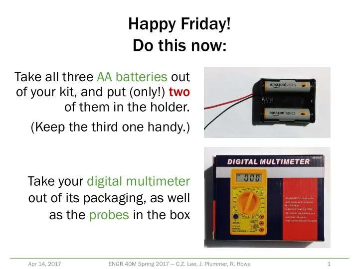
Take all three AA batteries out
- f your kit, and put (only!) two
- f them in the holder.
(Keep the third one handy.)
Happy Friday! Do this now:
Take your digital multimeter
- ut of its packaging, as well