lecture 27
play

Lecture 27 Logistics HW8 due Friday Ants problem due Friday Ants - PDF document

Lecture 27 Logistics HW8 due Friday Ants problem due Friday Ants problem due Friday Lab kit must be returned to Tony by Friday Review Sunday 12/7 3pm, Location TBD Last lecture State encoding One-hot encoding


  1. Lecture 27 � Logistics � HW8 due Friday � Ants problem due Friday � Ants problem due Friday � Lab kit must be returned to Tony by Friday � Review Sunday 12/7 3pm, Location TBD � Last lecture � State encoding � One-hot encoding � Output encoding � Today: � Optimizing FSMs � Pipelining � Retiming � Partitioning CSE370, Lecture 25 27 1 
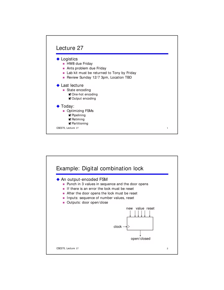
Example: Digital combination lock � An output-encoded FSM � Punch in 3 values in sequence and the door opens � If there is an error the lock must be reset � If there is an error the lock must be reset � After the door opens the lock must be reset � Inputs: sequence of number values, reset � Outputs: door open/close new value reset clock open/closed CSE370, Lecture 25 27 22 2

  2. Design the datapath value i C1 i C2 i C3 i C1 C2 C3 4 4 4 mux mux control control control control multiplexer 4 value comparator equal 4 � Choose simple control � 3-wire mux for datapath � 3 wire mux for datapath � Control is 001, 010, 100 � Open/closed bit for lock state equal � Control is 0/1 CSE370, Lecture 25 27 22 3 Output encode the FSM � FSM outputs � Mux control is 100, 010, 001 � Lock control is 0/1 � Lock control is 0/1 � State are: S0, S1, S2, S3, or ERR � Can use 3, 4, or 5 bits to encode � Have 4 outputs, so choose 4 bits � Encode mux control and lock control in state bits � Lock control is first bit, mux control is last 3 bits S0 = 0001 (lock closed, mux first code) S1 S1 = 0010 (lock closed, mux second code) 0010 (l k l d d d ) S2 = 0100 (lock closed, mux third code) S3 = 1000 (lock open) ERR = 0000 (error, lock closed) CSE370, Lecture 25 27 22 4

  3. Encode 4 state bits ERR closed A clever way for ERR is to use Preset/reset in existing flipflops. not equal not equal not equal & new & not equal & new & new S0 S1 S2 S3 closed closed closed start open equal equal equal mux= C1 mux= C2 mux= C3 & new & new & new not new not new not new Not equal & new Not equal & new Preset 0 = start Already in ERR S 0 + = S 0 N’ Preset 1,2,3 = 0 S 1 + = S 0 EN + S 1 N’ Reset 0 = start’(E’N + (Q 0 + Q 1 + Q 2 + Q 3 )’) S 2 + = S 1 EN + S 2 N’ Reset 1,2,3 = start + (E’N + (Q 0 + Q 1 + Q 2 + Q 3 )’) S 3 + = S 2 EN + S 3 CSE370, Lecture 25 27 26 5 S0 S0 D 0 = Q 0 N’ D 1 = Q 0 EN + Q 1 N’ D 2 = Q 1 EN + Q 2 N’ S0 D 3 = Q 2 EN + Q 3 E N S1 S1 N’ Preset 0 = start Preset 1,2,3 = 0 S1 Reset 0 = start’(E’N + (Q 0 + Q 1 + Q 2 + Q 3 )’) E Reset 1,2,3 = start + (E’N + (Q 0 + Q 1 + Q 2 + Q 3 )’) N S2 S2 N’ S0 S0 S2 S1 E S2 N S3 S3 CSE370, Lecture 25 27 26 6

  4. FSM design � FSM-design procedure 1. State diagram g 2. state-transition table 3. State minimization 4. State encoding 5. Next-state logic minimization 6. Implement the design CSE370, Lecture 25 27 26 7 Last topic: more FSM optimization techniques � Want to optimize FSM for many reasons beyond state minimization and efficient encoding � Additional techniques � Pipelining --- allows faster clock speed � Retiming --- can reduce registers or change delays � Partitioning --- can divide to multiple devices, simpler logic CSE370, Lecture 25 27 8

  5. Pipelining related definitions � Latency: Time to perform a computation � Data input to data output � Throughput: Input or output data rate � Typically the clock rate � Combinational delays drive performance d ≡ delay through slowest combinational stage � Define n ≡ number of stages from input to output � Latency ∝ n * d (in sec) � Throughput ∝ 1/d (in Hz) Th h t 1/d (i H ) CSE370, Lecture 25 27 9 Pipelining � What? � Subdivide combinational logic Logic Reg � Add registers between logic � Add registers between logic � Why? � Trade latency for throughput � Increased throughput � Reduce logic delays � Increase clock speed Logic Reg Logic Reg � May increased latency � Increase circuit utilization � Simultaneous computations CSE370, Lecture 25 27 10

  6. Reg Logic Reg Pipelining � When? � Need throughput more than latency � Signal processing � Signal processing � Logic delays > setup/hold times � Acyclic logic � Where? � At natural breaks in the combinational logic � Adding registers makes sense CSE370, Lecture 25 27 11 Retiming � Pipelining adds registers � To increase the clock speed � Retiming moves registers around � Reschedules computations to optimize performance � Change delay patterns � Reduce register count � Without altering functionality CSE370, Lecture 25 27 12

  7. Retiming examples � Reduce register count a D Q a a D Q D Q x x b d d D Q b � Change output delays CSE370, Lecture 25 27 13 FSM partitioning � Break a large FSM into two or more smaller FSMs � Rationale � Rationale � Less states in each partition � Simpler minimization and state assignment � Smaller combinational logic � Shorter critical path � But more logic overall � Partitions are synchronous � Same clock!!! � Same clock!!! CSE370, Lecture 25 27 14

  8. Example: Partition the machine � Partition into two halves C1 S1 S6 C2 C3 S2 S5 S3 C4 C5 S4 CSE370, Lecture 25 27 15 Introduce idle states � SA and SB handoff control between machines C1 S1 S1 S6 S6 C2 C3 S2 S5 S3 S4 C4 C5 C1 S6 S1 C1•S1 (C2•S6)’ (C2 S6) C2•S6 C2 (C1•S1+ C3•S2+ C3•S2+ SB S5 S2 SA C4•S3 C3+ C5 C4•S3+ C5•S2)’ C4 S3 C5•S2 S4 CSE370, Lecture 25 27 16

  9. Partitioning rules Rule # 1: Source-state transformation Replace by transition to idle state (SA) Replace by transition to idle state (SA) C1 C1 S1 S6 S1 SA Rule # 2: Destination state transformation Replace with exit transition from idle state p C2 C2• S6 S1 S6 S1 SA CSE370, Lecture 25 27 17 Partitioning rules (con’t) Rule # 3: Multiple transitions with same source or destination Source ⇒ Replace by transitions to idle state (SA) Destination ⇒ Replace with exit transitions from idle state C3 C3+C5 C3•S2 + S2 S5 S5 S2 C4•S3 SA SB C4 C5 C4 S3 S4 S3 S4 C5•S2 Rule # 4: Hold condition for idle state OR exit conditions and invert C2•S6 C2•S6 S1 SA CSE370, Lecture 25 27 18

  10. Mealy versus Moore partitions � Mealy machines undesirable � Inputs can affect outputs immediately � “output” can be a handoff to another machine!!! � output can be a handoff to another machine!!! � Moore machines desirable � Input-to-output path always broken by a flip-flop � But…may take several clocks for input to propagate to output CSE370, Lecture 25 27 19 Example: Six-state up/down counter � Break into 2 parts U ≡ count up U t D ≡ count down U S0 S5 U U D D D S1 S4 D D D D U U S2 S3 U CSE370, Lecture 25 27 20

  11. Example: 6 state up/down counter (con’t) � Count sequence S 0 , S 1 , S 2 , S 3 , S 4 , S 5 � S 2 goes to S A and holds, leaves after S 5 � S 5 goes to S B and holds, leaves after S 2 S t S d h ld l ft S � Down sequence is similar S0 S5 U•S5 U U U D D D•S0 D (D•S3 + (D•S0+ SA SA SB SB S1 S1 S4 S4 U•S5)’ U•S2)’ D•S3 D D D U U U•S2 U S2 S3 CSE370, Lecture 25 27 21 Minimize communication between partitions � Ideal world: Two machines handoff control � Separate I/O, states, etc. � Real world: Minimize handoffs and common I/O � Minimize number of state bits that cross boundary � Merge common outputs CSE370, Lecture 25 27 22

  12. Done! CSE370, Lecture 25 27 23

Download Presentation
Download Policy: The content available on the website is offered to you 'AS IS' for your personal information and use only. It cannot be commercialized, licensed, or distributed on other websites without prior consent from the author. To download a presentation, simply click this link. If you encounter any difficulties during the download process, it's possible that the publisher has removed the file from their server.

Recommend


More recommend