evaluation of structural behavior of lng insulation
play

EVALUATION OF STRUCTURAL BEHAVIOR OF LNG INSULATION SYSTEM UNDER - PDF document

18 TH INTERNATIONAL CONFERENCE ON COMPOSITE MATERIALS EVALUATION OF STRUCTURAL BEHAVIOR OF LNG INSULATION SYSTEM UNDER IMPACT LOADS S. J. Kim 1 , D. S. Han 1 , M. S. Chun 2 , S. E. Chun 2 , J. M. Lee 1 * 1 Naval Architecture and Ocean Engineering,


  1. 18 TH INTERNATIONAL CONFERENCE ON COMPOSITE MATERIALS EVALUATION OF STRUCTURAL BEHAVIOR OF LNG INSULATION SYSTEM UNDER IMPACT LOADS S. J. Kim 1 , D. S. Han 1 , M. S. Chun 2 , S. E. Chun 2 , J. M. Lee 1 * 1 Naval Architecture and Ocean Engineering, Pusan National University, Busan, Korea 2 Samsung Heavy Industries, Co., Ltd., Geoje 656-710, Republic of Korea * Corresponding author (jaemlee@pusan.ac.kr) Keywords : LNG carrier insulation system, Mark III, Sloshing, Dry drop test, Impact performance. compared with the without VIL IS experimental 1 Introduction results. In recent, a number of vast sizes of the LNG carrier 2 Experimental Apparatus (LNGC) are fabricated in industrial fields, and the size of the insulation system (IS) is rapidly increased 
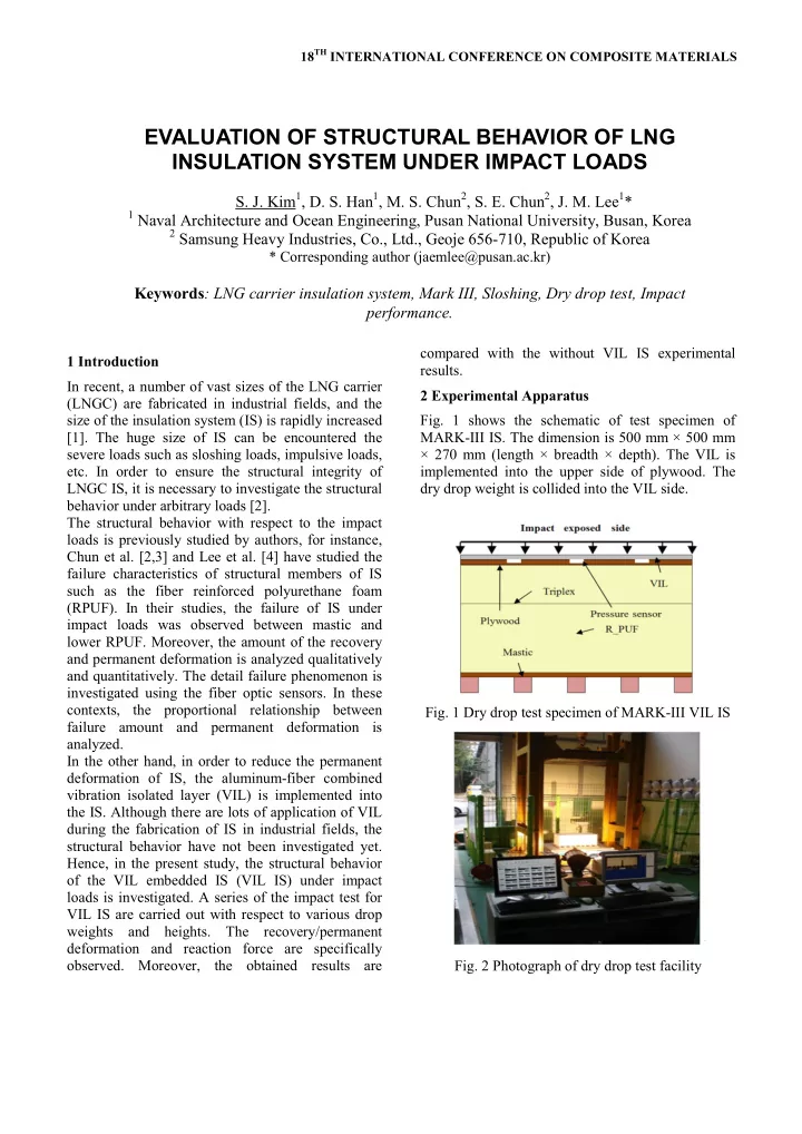
Fig. 1 shows the schematic of test specimen of [1]. The huge size of IS can be encountered the MARK-III IS. The dimension is 500 mm × 500 mm severe loads such as sloshing loads, impulsive loads, × 270 mm (length × breadth × depth). The VIL is etc. In order to ensure the structural integrity of implemented into the upper side of plywood. The LNGC IS, it is necessary to investigate the structural dry drop weight is collided into the VIL side. behavior under arbitrary loads [2]. The structural behavior with respect to the impact loads is previously studied by authors, for instance, Chun et al. [2,3] and Lee et al. [4] have studied the failure characteristics of structural members of IS such as the fiber reinforced polyurethane foam (RPUF). In their studies, the failure of IS under impact loads was observed between mastic and lower RPUF. Moreover, the amount of the recovery and permanent deformation is analyzed qualitatively and quantitatively. The detail failure phenomenon is investigated using the fiber optic sensors. In these contexts, the proportional relationship between Fig. 1 Dry drop test specimen of MARK-III VIL IS failure amount and permanent deformation is analyzed. In the other hand, in order to reduce the permanent deformation of IS, the aluminum-fiber combined vibration isolated layer (VIL) is implemented into the IS. Although there are lots of application of VIL during the fabrication of IS in industrial fields, the structural behavior have not been investigated yet. Hence, in the present study, the structural behavior of the VIL embedded IS (VIL IS) under impact loads is investigated. A series of the impact test for VIL IS are carried out with respect to various drop weights and heights. The recovery/permanent deformation and reaction force are specifically observed. Moreover, the obtained results are Fig. 2 Photograph of dry drop test facility

  2. Table 1 Scenarios of dry drop test Fig. 2 shows the photograph of the dry drop test facility for MARK-III VIL IS. The dry drop weight Weight Height Thickness No and height are 3 m and 260/680 kgf, respectively. In (kgf) (m) of damper (VIL) order to obtain the various impact energies, the air 1 - pressure device is implemented. The original dry 0.5 drop speed is 6.0 m/s and the additional speed using 2 2.5 mm air pressure device is 8.5 m/s. 3 - Table 1 shows the test scenarios of the present study. 1.0 m The drop times of Test No. 1-20 and Test No. 21-28 4 2.5 mm are single and 10 times (cyclic), respectively. In 5 - order to investigate the structural behavior under 1.5 m cyclic impact loads, the 10 times of dry drop test are 6 2.5 mm carried out. Fig. 3 shows the custom-built-type reaction force- 7 - 2.0 m displacement measurement system. The relationship 8 2.5 mm between reaction force and time can be obtained by the load sensors and the dynamic strain logger. In 9 - addition, the relationship between displacement and 10 3.0 mm time can be acquired by the high speed/quality 260 kgf 2.5 m camera and track eye motion analysis (TEMA) 11 6.0 mm program. In the present study, the deformation was 12 9.0 mm captured 1,000 figures per second. The deformation can be specifically measured by tracking the 13 - reference point on the IS using TEMA program. 14 3.0 mm 3.0 m 15 6.0 mm 16 9.0 mm 17 - 18 3.0 mm 3.0 m (pressurized) 19 6.0 mm 20 9.0 mm 21 - 22 3.0 mm 0.5 m 23 6.0 mm 24 9.0 mm 680 kgf 25 - 26 3.0 mm Fig. 3 Photograph of custom-built-type reaction 1.0 m force-displacement measurement system 27 6.0 mm 28 9.0 mm

  3. STRUCTURAL EVALUATION OF IMPACT LOAD IN LNG INSULATION SYSTEM 3. Results and Discussions Fig. 4 shows the representative relationship between reaction force and time when the drop weight and height are 680 kgf and 0.5 m, respectively. Fig. 5 shows the representative relationship between deformation and time during the drop weight and height are 680 kgf and 0.5 m, respectively. As shown in Fig. 4, two kinds of peak reaction force were observed at 4 ms and 8 ms. At this moment, the maximum pressure was 10-32 bar. According to the related previous studies such as Bass et al. [5], the conservative sloshing pressure of LNGC IS is 24.5 bar. Therefore, it is confirmed that the experimental results of the present study are reasonable. In addition, the first peak of the reaction force of the VIL IS is less than the without VIL IS. However, in the second peak of the reaction force, the amount is Fig. 5 Relationship between deformation and time at same each other. It is considered that the first weight 680 kgf, height 0.5 m drop test reaction force is reduced because of the damping effect of VIL. Nevertheless, the second reaction force is not related to the VIL. Hence, using the VIL, a certain level of reaction force can be prevented, and the slight impact damage due to the impact/sloshing force can be reduced. As shown in Fig. 5, the maximum deformation was observed at 8- 10 ms, and the recovery/permanent deformations were also measured after 8-10 ms. The maximum and permanent deformations of the VIL IS is less than the without VIL IS. Hence, it is confirm that the VIL can considerably diminish the deformation induced by impact loads. Fig. 6 Relationship between maximum displacement and thickness of VIL regarding to cyclic impact loads at weight 680 kgf, height 0.5 m drop test Fig. 6 shows the relationship between the maximum displacement and the thickness of VIL regarding to the cycles of impact loads. As shown in this figure, as the cycles are increased, the maximum displacement was increased. Moreover, as the thickness of VIL is increased, the maximum displacement was decreased. According to the cyclic drop test, it is considered that the VIL IS became crushed as the impact loads are repeated, and the Fig. 4 Relationship between reaction force and time maximum displacement is quite sensitive to the at weight 680 kgf, height 0.5 m drop test 3

  4. [3] M. S. Chun, M. H. Kim, W.S. Kim, S. H. Kim, J. M. thickness of VIL. Hence, it is important to design the Lee, “Experimental Investigation on the Impact adequate thickness of VIL in order to ensure the Behavior of Mem-brane Type LNG Carrier Insulation robust IS under impact/sloshing loads. System”, Journal of Loss Prevention in the Process The experimental results are summarized in Tables 2 Industries, Vol. 22, (2009), pp. 901-907 and 3. [4] J.M. Lee, J.K. Paik, M.H. Kim, J.W. Yoon, I.H. Choe, W.S. Kim and B.J. Noh, “Strength of membrane type Table 2 Experimental results of test scenario No. 1-8 LNG cargo containment system under sloshing Maximum force (kN) Maximum displ.(mm) Weight Height impact”, Proc. of the World Maritime Technology (kgf) (m) 0 2.5 0 2.5 Conference, London, UK (2006) [5] R. L. Bass, E.B. Bowles and P.A. Cox, “Liquid 0.5 270 263 1.9 1.9 Dynamic Loads in LNG Cargo Tank”, Paper 1.0 406 392 3.5 2.9 260 presented at annual meeting, The Society of Naval 1.5 513 463 7.4 5.7 Architects and Marine Engineers, (1980), New York, 2.0 579 577 8.2 8.3 USA Table 3 Experimental results of test scenario No. 9-28 Maximum force (kN) Maximum displ.(mm) Weight Height (kgf) (m) 0 3 6 9 0 3 6 9 2.5 650 665 660 621 7.9 7.8 7.1 6.9 260 3.0 728 732 722 698 9.5 8.4 8.0 8.4 C 815 758 782 771 11.4 10.2 9.5 8.3 Maximum force (kN) Maximum displ.(mm) Weight Height (kgf) (m) 0 3 6 9 0 3 6 9 0.5 520 487 458 458 5.5 3.8 4.6 3.8 680 1.0 833 803 775 667 7.6 7.1 7.7 6.1 Acknowledgment This research was supported by the Basic Science Research Program through the National Research Foundation of Korea (NRF), funded by the Ministry of Education, Science and Technology (2011- 0003879). The authors are pleased to acknowledge the support of Samsung Heavy Industries, Co., Ltd. References [1] Mateusz Graczyk, Torgeir Moan, “A probabilistic assessment of design sloshing pressure time histories in LNG tanks”, Ocean Engineering, Vol. 35, (2008), pp. 834-855 [2] M.S. Chun, H. Ito, Y.S. Suh, W.S. Kim, B.J. Noh, J.H. Yoon, M.S. Kim, H.S. Urm, M.H. Kim, D.S. Han, J.M. Lee "A comparative study on the impact damage of membrane type LNGC insulation system", Proc. of 28th International Conference on Ocean, Offshore and Arctic Engineering, (2009), Hawaii, USA

Download Presentation
Download Policy: The content available on the website is offered to you 'AS IS' for your personal information and use only. It cannot be commercialized, licensed, or distributed on other websites without prior consent from the author. To download a presentation, simply click this link. If you encounter any difficulties during the download process, it's possible that the publisher has removed the file from their server.

Recommend


More recommend