
SLIDE 1
ESS 439 lab 2
Isotropic materials, Anisotropic minerals
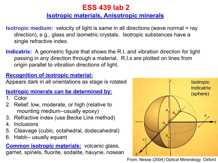
Isotropic medium: velocity of light is same in all directions (wave normal = ray direction), e.g., glass and isometric crystals. Isotropic substances have a single refractive index. Indicatrix: A geometric figure that shows the R.I. and vibration direction for light passing in any direction through a material. R.I.s are plotted on lines from
- rigin parallel to vibration directions of light.
Isotropic Indicatrix: (sphere)
Recognition of isotropic material: Appears dark in all orientations as stage is rotated Isotropic minerals can be determined by:
- 1. Color
- 2. Relief: low, moderate, or high (relative to
mounting medium--usually epoxy)
- 3. Refractive index (use Becke Line method)
- 4. Inclusions
- 5. Cleavage (cubic, octahedral, dodecahedral)
- 6. Habit-- usually equant