SLIDE 1 ESS 439 lab 2
Isotropic materials, Anisotropic minerals
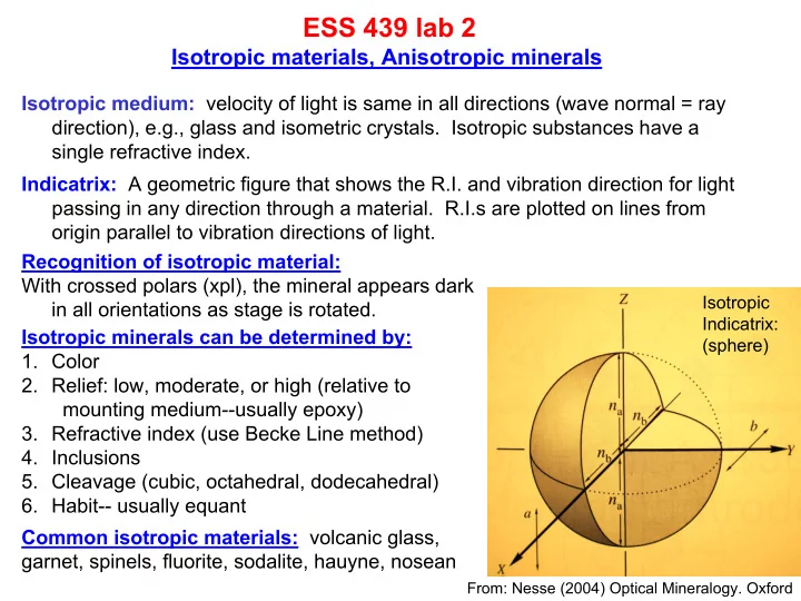
Isotropic medium: velocity of light is same in all directions (wave normal = ray direction), e.g., glass and isometric crystals. Isotropic substances have a single refractive index. Indicatrix: A geometric figure that shows the R.I. and vibration direction for light passing in any direction through a material. R.I.s are plotted on lines from
- rigin parallel to vibration directions of light.
Isotropic Indicatrix: (sphere)
Recognition of isotropic material: With crossed polars (xpl), the mineral appears dark in all orientations as stage is rotated. Isotropic minerals can be determined by:
- 1. Color
- 2. Relief: low, moderate, or high (relative to
mounting medium--usually epoxy)
- 3. Refractive index (use Becke Line method)
- 4. Inclusions
- 5. Cleavage (cubic, octahedral, dodecahedral)
- 6. Habit-- usually equant
Common isotropic materials: volcanic glass, garnet, spinels, fluorite, sodalite, hauyne, nosean
From: Nesse (2004) Optical Mineralogy. Oxford
SLIDE 2 Lab 2 (cont.) Refractometry
Refractive Index is measured in a grain mount by immersing grains of minerals (or glass) in an
- il of known refractive and observing the
movement of the Becke line. Use plane polarized light, medium or high power
- bjective and partially closed iris diaphragm
If nmineral ≠ noil, a thin line of white light at the grain boundary (Becke line) will move into the grain as the objective is raised above focus if ngrain > noil or will move into the oil if noil > ngrain If the n’s are the same the grain will be invisible. Actually, two colored lines (red) and blue) should appear because n is a function of λ (dispersion). These lines will move in opposite directions as the
- bjective is raised or lowered from the focus
- position. This may be difficult to see.
For precise work, use a Na lamp (λ = 539 nm). n
- f the oil is then measured in a Abbe refractometer
From: Nesse (2004) Optical Mineralogy. Oxford
SLIDE 3 Lab 2 (cont.) Exercises
- 1. If we have time, we will prepare grain mounts and demonstrate the technique
- 2. Locate the following thin sections and answer the questions
- 3. Mauna Loa (basalt): Sections should be 30 microns thick. Phenocrysts are olivine.
Using plane polarized light (analyzer out) (i) Does olivine show any color, cleavage or crystal faces? Using crossed polars (analyzer in) (ii) What colors do you see? Are these colors the same for all olivines? (iii) Describe what happens as the stage is rotated through 360° (iv) Select an olivine, rotate stage until “extinct”, rotate 45°cw , insert gypsum plate and describe what you see. Repeat after rotating 45°ccw 4 Adamello (granodiorite, Italy): Locate a biotite crystal showing good cleavage (i) Using ppl, record the color of biotite when cleavage is E-W and N-S. (ii) Locate biotite showing no cleavage, and describe color changes (if any) (iii) Using xpl, describe what happens as the stage is rotated
- a. 152-11-28 or 152-29-17 or 175-40-3 (mid ocean ridge basalt from Juan de
Fuca). The brown material is volcanic glass. How might the glass form?
- b. Lab 574 or 597 or 571. Locate the isotropic mineral. Determine the RI of the
isotropic mineral relative to the other minerals in the section.
- c. Hansen Lake: Locate the isotropic mineral and determine its relative RI.
- d. KH-1 or BSQ 35: Locate the isotropic mineral, determine relative RI and color
- e. 1505 Flow or CV 61 or CV59: Locate and describe & sketch the blue mineral.
SLIDE 4 Lab 2b Anisotropic minerals: General discussion
Anisotropic mins: Vlight depends on orientation of ray path and they exhibit double refraction (light splits into 2 rays vibrating at right angles and each ray has different V) Two groups: (1) Uniaxial minerals (tetragonal, hexagonal/trigonal systems) have one direction (c axis—called the optic axis) along which mineral behaves isotropically. (2) Biaxial minerals (orthorhombic, monoclinic, triclinic systems) have two directions (2 optic axes) along which mineral behaves isotropically. Calcite double refraction experiment (calcite is trigonal and uniaxial). The two rays are referred to as the ordinary ray (ω) and the extraordinary ray (ε). The ε ray vibrates in a plane containing the c-axis and the ray path and ω vibrates at right angles to c-axis and ray path. The R.I. of ω ray is nω and R.I. of the ε ray is nε.
Select a clear calcite rhomb and place the rhomb above a small dot on a sheet of paper in orientation
- shown. You will see two dots produced by
refraction of the ε and ω rays. One dot (corresponding to ω) will appear shallower that the
- ther (ε). The ε ray will describe a circle around the
- ther dot as the rhomb is rotated. Place a piece of
polaroid film on the rhomb with its privileged direction oriented N-S. One dot will disappear. Which one? Rotate the film 90º and repeat. The
- ther dot disappears. Why?
Explain your observations with diagrams.
From: Nesse (2004) Optical Mineralogy. Oxford
SLIDE 5 Retardation and interference colors
Ray of polarized light passing into an anisotropic mineral slice of thickness d is resolved into two orthogonal rays with different velocities and wavelengths
From: Nesse (2004) Optical Mineralogy. Oxford
Slow ray “lags” behind fast ray by distance ∆ (retardation) ∆ = d(ns – nf). ns-nf is called the birefringence (δ) and it is a function of the orientation of the mineral relative to the light path. Paths along an optic axis will have zero δ while paths ┴ optic axis will have maximum δ. Other paths will have intermediate δ. With white light, δ will result in a distinctive interference color after passing through analyzer. ∆=dδ With white light, all λ’s are present and each λ is split into a fast and a slow ray. At any give d, ∆ is pretty much constant for each λ. In this case, some λ’s reach the analyzer in-phase and are cancelled while others are out-
- f-phase and are transmitted. The combination of different
λ’s that pass through the analyzer produce the interference
- color. In summary, the interference color observed
depends on the thickness of the mineral slice, its crystallographic orientation and its birefringence.
SLIDE 6 Retardation and interference (cont.) (a) Monochromatic light. The slow ray lags behind the fast ray; in this example by exactly
- ne wavelength (∆=1λ). When the ray enters
the analyzer it is resolved into a vibration direction 90º to the privileged direction of the analyzer and is therefore cut out.
From: Nesse (2004) Optical Mineralogy. Oxford
(b) Monochromatic light. The slow ray lags behind the fast ray; in this example by exactly
- ne-half wavelength (∆=½λ). When the ray
enters the analyzer it is resolved into a vibration direction parallel to the privileged direction of the analyzer and is transmitted. ∆=1λ ∆=½λ
SLIDE 7
Retardation, interference and colors (cont.) Interference colors result when polychromatic light (white light) is used. Nesse (eqn 5.5) shows that: T = 100*(sin2(180º(∆/λ))) where T = % transmission when the mineral is rotated to the 45º position (from extinction). (a) ∆ = 250 nm All λ’s are out-of-phase so all λ’s are transmitted to produce a white interference color (first order white). Example: quartz.
∆ = .009 x 30 x 1000 nm = 270 nm
(a) ∆ = 500 nm Primarily red and violet transmitted to give first order red, e.g., tourmaline
∆ = .016 x 30 x 1000 nm = 480 nm
(a) ∆ = 2500 nm Mineral with very high birefringence, e.g., calcite, produces white interference color of a high order.
∆ = .172 x 30 x 1000 nm = 5160 nm
Interference colors are shown on the color chart with change from red to blue occurring at ~550, 1100, 1650 nm producing “orders” of colors.
From: Nesse (2004) Optical Mineralogy. Oxford
SLIDE 8
Interference Color Chart
Birefringence Thickness (mm) Path difference (nm)
200 400 600 800 1000 1200 1400 1600 1800 2000 2200 First order Second order Third order Fourth order 550 1100 1650
SLIDE 9
Interference Color Chart
SLIDE 10
Other optical phenomena in anisotropic minerals
Pleochroism: Viewed in plane polarized light (ppl) Mineral color produced by differential absorption of different λ’s Observed as a color change as the stage is rotated as the different vibration directions are aligned parallel to the E-W polarizer Colors are listed accordingly, e.g., for tourmaline ε = pale green ω = dark green Extinction: Viewed under crossed polars (xpl) Mineral will go “extinct” (appear dark) four times during a 360° stage rotation as vibration directions coincide with the orientation of the polarizer and analyzer Extinction angle is measured relative to a known crystallographic direction Types of extinction: Parallel: mineral goes extinct when a prominent crystallographic direction or cleavage is parallel to the cross hairs, e.g., in hexagonal and tetragonal minerals one vibration direction is always parallel to the c-axis. Inclined: mineral goes extinct when a prominent crystallographic direction or cleavage s at an angle (the extinction angle) to the cross hairs (common in monoclinic and triclinic minerals) Symmetrical: when the extinction position bisects the angle between two prominent crystallographic directions, e.g., pyroxenes and amphiboles No extinction angle: some minerals do not show prominent faces or cleavages
SLIDE 11 Determination of fast and slow rays using accessory plate Other optical phenomena in anisotropic minerals (cont.)
Gypsum plate ∆=530 nm Mica plate ∆=147 nm slow empty
a b In this example, we would like to know which is the slow ray and which is the fast ray. First, rotate mineral to its extinction position. a b Rotate stage 45º and observe interference color a b Third: Insert gypsum plate and observe the interference
- colors. Using the color chart determine if the interference
color increases or decreases. Slow on slow will increase the int. color and slow on fast will decrease the int. color. If the a vibration direction is slow relative to b, int. color will decrease and vice versa. s f