
SLIDE 1
Emergency Power Systems
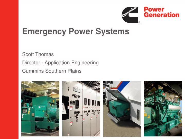
Scott Thomas Director - Application Engineering Cummins Southern Plains
Emergency Power Systems Scott Thomas Director - Application - - PowerPoint PPT Presentation
Emergency Power Systems Scott Thomas Director - Application Engineering Cummins Southern Plains Agenda Generator Application Considerations Ratings Diesel vs Natural Gas Common Design Challenges Packaging Enclosures and
Scott Thomas Director - Application Engineering Cummins Southern Plains
– Ratings – Diesel vs Natural Gas – Common Design Challenges
– Emissions – Common Generator Failures – Maintenance Recommendations
– Basic Functionality – Open and Closed Transition – ATS Types
– Recirculation of radiator discharge air – Proximity to ATS - Transformer
– Fire Pumps – WWTP/LS/PS – VFD’s - Harmonics
Cummins Confidential
– Engine noise
– Cooling fan noise
– Alternator noise
– Structural/mechanical noise
– Un-silenced engine exhaust
– Sound pressure drops ~6 dBA at 2x distance
– Perceived sound pressure increases 3dBA due to a reflective surface; 5dBA for two reflective surfaces
– Radiator discharge turning vanes (Scoop) – Engine Exhaust elbows
– Fuel Fill – Load Bank Connections
– Snow Loading / Plowing – Flood Plain
– Windows/Doors – Ventilation Intakes
– Dedicated space – Working space (36” or 1 m minimum) – Working height
– Additional equipment space – Future genset capacity – Replacement parts access
– Contact Fire Marshall for volume, tank construction expectations, and field testing requirements – Access and filling for rooftop installations – Actual run time required/desired
– Cold - Waxing point of particular diesel blend on-site – Warm – Fuel return temperature in small tanks
– Overfill protection valves (OFPV) – Spillboxes – Fuel level alarms – Polishing systems – Remote Fill Stations – Elevated Vents
– Auxiliary pump or gravity return
– Utilize genset subbase tank with additional ports – Standalone day tank from 3rd party supplier
– Limit fittings, bends, and length of runs
EPA SI NSPS Final Rule
Stationary Emergency Engine Designated Use for NSPS and RICE NESHAP
– Utility failure, transformer, UPS, circuit breaker, ATS – Document issue as a part of record keeping requirement
– Dead Batteries (Redundant Battery String & BBS) – Battery Charger Failure (Redundant Battery String & BBS) – Fuel Quality (Fuel Filtration Systems, Fuel Maintenance Program) – Low Coolant Levels (Periodic Inspection – Alarm) – Control not in Auto (Remote Annunciator – SCADA Alarm) – Circuit Breaker Open (Remote Annunciator – SCADA Alarm)
– Quarterly Inspections – Annual Oil/Filter Change – Annual Supplemental Load Bank Testing
– Battery Replacement
years.
– Annual Fluid Sampling
– ATS Inspections
electrical loads between two sources of power by using either automatic or manual controls
and frequency
starts and accelerates to rated speed and voltage
What is a Transfer Switch?
switch
Transition Types and Applications
Programmed Transfer)
Open Transition – Utility to Genset
Utility Power Fails Generator Starts Gen Source Available Load Transfers to Generator
Open Transition – Genset to Utility
Utility Power Returns ATS retransfers load to Utility ATS removes gen run command
From Utility To Loads Load (Residual) Voltage Utility/Genset Voltage
Time Delayed Transition
INDUCTIVE LOAD UTILITY UTILITY UTILITY LOAD VOLTAGE
Pre-determined delay allows the residual voltage to decay
TIME INDUCTIVE LOAD INDUCTIVE LOAD
Time Delayed Transition
Closed Transition
From Utility To Loads
LOAD UTILITY LOAD UTILITY LOAD UTILITY TIME LOAD VOLTAGE
Up to 10s of power interruption
Full power outage cycle (utility drops out)
LOAD UTILITY LOAD UTILITY LOAD UTILITY TIME LOAD VOLTAGE
Up to 100ms of paralleled operation
Return to Normal Power (After Outage)
Closed Transition Risks
– Current flow between sources caused by a difference in instantaneous voltage between sources at the instant of closure
– Phase angle difference between sources – Difference in RMS voltage between sources – Transient condition on one of the sources
– Frequency and Voltage shift due to less than perfect synchronization – Current spike may result due to voltage difference – Disturbances minimized by Load sequencing
relays
additional utility regulations
Closed Transition Considerations
power to critical loads.
connected in parallel, the bypass transfer switch adds redundancy to the system
– Critical power and maintenance requirements, including data centers,health care, and waste water treatment facilities
Bypass Isolation Switches
ATS Bypass
N L E
Bypass Transition Switch
ATS Bypass
N L E
ATS Bypass
N L E
ATS Bypass
N L E
Connected Test Isolated
when to Bypass to same source
load interruption
emergency power
Isolation Bypass Positions
switches
– Remote monitoring of “Switch not in auto”
– Non Load break
Bypass Isolation Considerations
breaker on the utility side
– The breaker is a UL listed over- current device
Service Entrance equipment
– Saves space and cost for a separately mounted circuit breaker
Service Entrance Transfer Switch
Breaker Pair Transfer Switch
Breaker Pair Transfer Switch
– Integral over current protection – Draw out capability (easier to service)
– Closed transition with soft loading (option) – Can be also offered as a Service Entrance switch – Facilitates selective coordination - can withstand fault current up to 60 cycles – High level of serviceability