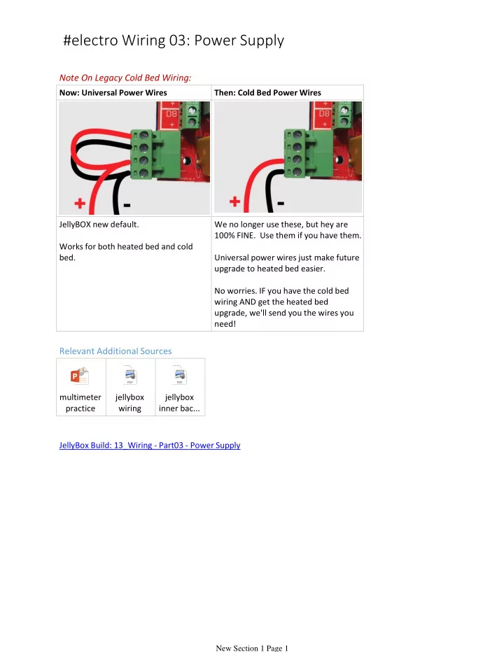

#electro Wiring 03: Power Supply Note On Legacy Cold Bed Wiring: Now: Universal Power Wires Then: Cold Bed Power Wires JellyBOX new default. We no longer use these, but hey are 100% FINE. Use them if you have them. Works for both heated bed and cold bed. Universal power wires just make future upgrade to heated bed easier. No worries. IF you have the cold bed wiring AND get the heated bed upgrade, we'll send you the wires you need! Relevant Additional Sources multimeter jellybox jellybox practice wiring inner bac... JellyBox Build: 13_Wiring - Part03 - Power Supply New Section 1 Page 1
In this video, we learn how NOT TO blow up the electronics by verifying the power supply with a multimeter. We also wire up the power wires. _________________________________________________________________ Title: Testing the Parts with a Multimeter You'll Need: New Section 1 Page 2
Power supply Multimeter (you can build the printer without one, but it's great for double checking and trouble shooting. Your local makerspace / school / physics teacher / handy neighbor has one.) Title: Testing the Switch Note: This portion of the guide is basically a multimeter practice and switch exploration. Set your multimeter for continuity testing. In this mode, completing a circuit makes the meter beep. Place the probes on the contacts of the switch. Check that 'on' beeps and 'off' does not :-) That's what a switch should do. New Section 1 Page 3
Title: Test the Power Supply Note: This portion of the guide is basically a multimeter practice and power supply exploration. RED is always PLUS. "Red is Fab." Fab means positive. That means plus. Put the multimeter in voltage mode. Plug in the power supply (into an outlet that is.) Place the red probe inside the power supply connector. Place the black probe on the outer surface of the connector. You should see 12-point-something volts. Title: Insert the Power Supply Connector New Section 1 Page 4
Disconnect the power supply connector from the harness. Remove the nut and spring washer from the back of the connector. Insert the connector into the case from the outside. Slide the spring washer and nut over the wires. Tighten everything using vise grip and the IMADE3D wrench. Title: Insert the Power Switch New Section 1 Page 5
Remove the nut from the front of the switch. Place the switch into the "Big Friendly Button" hole from the inside. Replace the nut to hold the switch in place. You can tighten it easily by tilting the switch towards you and then holding the nut with the IMADE3D wrench before turning the switch back. Title: Reconnect the Wires New Section 1 Page 6
Reconnect the spade connectors on the wiring harness. New Section 1 Page 7
Here's an overview of the Universal Bed wiring. The power supply connects to ALL FOUR terminals of the green connector. New Section 1 Page 8
Red is always plus! Red wires MUST connect to plus, or you WILL burn your board. There are little pluses right next to the connector. The wires ends (ferrules) are thick; you'll need to fully open the connector. Title: Secure the Power Wire New Section 1 Page 9
Run the remaining wire through the loops of the 4" zip ties you placed earlier along the bottom edge. You can leave these fairly loose. Snip off the tails to keep things tidy when you're done. Title: Test the Power Supply AND Turn on the JellyBOX New Section 1 Page 10
Note: We're double and triple checking because we really don't want to destroy the printer. It's a good policy. Disconnect the green header from the RAMPS board. Connect the power supply. Turn on the switch. Set your multimeter to voltage mode. Measure the voltage on the screws in the green disconnected connector- red to red, black to black. You should have 12-point-something volts with no minus sign, Title: Power Up the RAMPS Board New Section 1 Page 11
Make sure the power is switched off. Reconnect the header to the RAMPS board. Turn the power on. You should see a red LED in the upper left corner on the board blink twice. If you smell anything bad turn off the power immediately and investigate. Title: Connect the LCD Screen Make sure the power is off. Connect the LCD screen to the headers on the right side of the RAMPS board. Turn the power on. AND BEHOLD. You should see the message "IMADE3D JELLYBOX WAKING UP" or similar. Afterwards it will show "MINIMUM TEMPERATURE ERROR" - this is fine. It just means we have not connected the temperature sensor yet :-) New Section 1 Page 12
means we have not connected the temperature sensor yet :-) New Section 1 Page 13
Recommend
More recommend