RC delay 4: The Elmore delay - 3 Application of the Elmore delay - - PowerPoint PPT Presentation

rc delay 4 the elmore delay 3
SMART_READER_LITE
LIVE PREVIEW

RC delay 4: The Elmore delay - 3 Application of the Elmore delay - - PowerPoint PPT Presentation

RC delay 4: The Elmore delay - 3 Application of the Elmore delay formula to a (RC) wire. Let R , C , and l be the total line resistance, capacitance, and length. = = = / ; / ; / r R l c C l L l N N ( ) ( ) ( ) 2


slide-1
SLIDE 1

EEL7312 – INE5442 Digital Integrated Circuits 1

RC delay – 4: The Elmore delay - 3

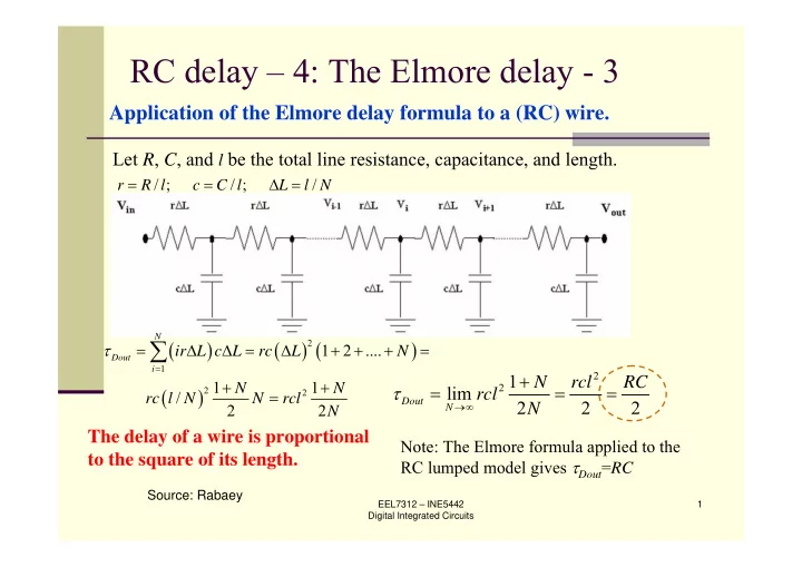
Let R, C, and l be the total line resistance, capacitance, and length.

Application of the Elmore delay formula to a (RC) wire.

/ ; / ; / r R l c C l L l N = = Δ =

( ) ( ) ( ) ( )

2 1 2 2

1 2 .... 1 1 / 2 2

N Dout i

ir L c L rc L N N N rc l N N rcl N τ

=

= Δ Δ = Δ + + + = + + =

2 2 1

lim 2 2 2

Dout N

N rcl RC rcl N τ

→∞

+ = = = The delay of a wire is proportional to the square of its length.

Note: The Elmore formula applied to the RC lumped model gives τDout=RC

Source: Rabaey

slide-2
SLIDE 2

EEL7312 – INE5442 Digital Integrated Circuits 2

RC delay – 5: The Elmore delay - 4

Example 4.8 of Rabaey’s book: 10-cm-long, 1- μm-wide Al1 wire

for which r=0.075 Ω/ μm, c= 110 aF/μm.

( )

2 2 5

/ 2 0.075 /μm 110aF/μm 10 μm / 2 41.3 ns

Dout

rcl τ = = Ω ⋅ ⋅ =

Note: The Elmore delay is, in general, not equal to the delay time. For a distributed RC network, the Elmore delay τD = 0.5 RC whereas the delay time td = 0.38 RC

Source: Rabaey

slide-3
SLIDE 3

EEL7312 – INE5442 Digital Integrated Circuits 3

RC delay – 6

Example 4.8 of Rabaey’s book: 10-cm- long, 1- μm-wide Al1 wire for which r=0.075 Ω/ μm, c= 110 aF/μm.

Distributed RC line 1 * this is DistributedRCline.cir file v0 1 0 dc 0 pulse 0 1V 0 10ps 10ps 200ns 400ns URC1 1 2 0 MURC L=100m .model MURC URC rperl=75k cperl=110p .end SpiceOpus (c) 7 -> source DistributedRCline.cir SpiceOpus (c) 8 -> tran 1ns 200ns SpiceOpus (c) 9 -> setplot new New plot Current tran2 Distributed RC line 1 (Transient Analysis) SpiceOpus (c) 10 -> setplot tran2 SpiceOpus (c) 11 -> plot v(2) xlabel time ylabel Vout

lumped distributed

slide-4
SLIDE 4

EEL7312 – INE5442 Digital Integrated Circuits 4

RC delay – 7

Diffusion equation

Source: Rabaey

slide-5
SLIDE 5

EEL7312 – INE5442 Digital Integrated Circuits 5

RC delay – 8

Step-response of RC wire as a function of time and space

Source: Rabaey

0.5 1 1.5 2 2.5 3 3.5 4 4.5 5 0.5 1 1.5 2 2.5 time (nsec) voltage (V) x= L/10 x = L/4 x = L/2 x= L

slide-6
SLIDE 6

EEL7312 – INE5442 Digital Integrated Circuits 6

RC delay – 9

0.9 RC 2.2 RC 10→90% (tr) 0.5 RC RC 0→63% (τ) 0.38 RC 0.69 RC 0→50% (tp) Distributed RC network Lumped RC network Voltage range

Source: Rabaey

slide-7
SLIDE 7

EEL7312 – INE5442 Digital Integrated Circuits 7

RC delay – 10

Source: Rabaey

Vout Driver cwire

Vin C Rdriver Vout L

rw, cw, L

When are the effects of the wire delay important? Assume that the driver delay is tpgate. The wire delay is

2

0.38 0.38

pwire w w

t RC r c L = =

The wire delay is important when tpwire≅tpgate or, equivalently

0.38

pgate crit w w

t L r c =

slide-8
SLIDE 8

EEL7312 – INE5442 Digital Integrated Circuits 8

RC delay – 11

Example 4.8 of Rabaey’s book: 10-cm- long, 1- μm-wide Al1 wire for which r=0.075 Ω/ μm, c= 110 aF/μm.

Distributed RC line 2 * this is DistributedRCline2.cir *file * the rise time is of the order of the *RC time constant v0 1 0 dc 0 pulse 0 1V 0 50ns 50ns +200ns 500ns URC1 1 2 0 MURC L=100m .model MURC URC K=2 +fmax=20G rperl=75k cperl=110p .end Response to pulse rise time=0 Response to pulse rise time=50 ns Note that the internal resistance of the voltage source is zero in this example

What if the rise time becomes much higher than RC?

slide-9
SLIDE 9

EEL7312 – INE5442 Digital Integrated Circuits 9

RC delay – 12

Example 4.8 of Rabaey’s book: 10-cm- long, 1- μm-wide Al1 wire for which r=0.075 Ω/ μm, c= 110 aF/μm.

What if the rise time becomes much higher than RC?

slide-10
SLIDE 10

EEL7312 – INE5442 Digital Integrated Circuits 10

RC delay – 13

Source: Weste&Harris

slide-11
SLIDE 11

EEL7312 – INE5442 Digital Integrated Circuits 11

RC delay – 14

Source: Rabaey

Design Rules of Thumb

rc delays should only be considered when tpRC >>

tpgate of the driving gate

Lcrit >> √ tpgate/0.38rc

rc delays should only be considered when the rise

(fall) time at the line input is smaller than RC, the rise (fall) time of the line

trise < RC

when not met, the change in the signal is slower than

the propagation delay of the wire

slide-12
SLIDE 12

EEL7312 – INE5442 Digital Integrated Circuits 12

I + VL

  • Inductance - 1

/

L

V LdI dt =

2 / 2 L

E LI =

Inductive effects important for power grids (high current), clock networks

(high speed), and wide busses (low resistance/unit length); may cause ringing/overshoot effects, reflection of signals, inductive coupling between lines (crosstalk), and switching noise in power lines Clock trees and power/ground grid need to be designed carefully to avoid large clock skew, signal inductive coupling and ground bounce

slide-13
SLIDE 13

EEL7312 – INE5442 Digital Integrated Circuits 13

Inductance - 2

Inductance of a wire depends on its geometry and surrounding dielectric Extracting the inductance is in general a 3-D problem and is extremely time-consuming for complex geometries Inductance depends on the entire current loop; it is impractical to extract the inductance from a chip layout

Source: Rabaey, Weste&Harris

slide-14
SLIDE 14

EEL7312 – INE5442 Digital Integrated Circuits 14

Inductance - 3

The Wave Equation

Vin Vout r c r r x c r c c l l l l

The Transmission Line

Source: Rabaey

When r=0 → signal travels at speed of light, which is smaller than speed of light in vacuum (300 mm/ns). In the real case, currents return in distant power lines and increase inductance thus reducing signal velocity. When l=0 → rc wire (diffusion equation)

slide-15
SLIDE 15

EEL7312 – INE5442 Digital Integrated Circuits 15

Inductance - 2

Source: Qi, CICC 2000

slide-16
SLIDE 16

EEL7312 – INE5442 Digital Integrated Circuits 16

Crosstalk is the coupling of energy from one line to another via:

Mutual capacitance (electric field) Mutual inductance (magnetic field)

Mutual Capacitance, Cm Mutual Inductance, Lm

Source: Intel

Zs Zo Zo Zo Zs Zo Zo Zo Cm Lm near far near far