
SLIDE 1
Electro Magnetic Impact Treatment Outline Goals and vision - - PowerPoint PPT Presentation
Electro Magnetic Impact Treatment Outline Goals and vision Nomasicos main activity is the introduction and management of novel industrial services and products, with the prospect of introducing significant changes in manufacture via the
Nomasico’s main activity is the introduction and management of novel industrial services and products, with the prospect of introducing significant changes in manufacture via the introduction and establishment its innovative techniques.
Nomasico Strategic goals
Development, management and realization of novel production methods and services. Clientele selection in accordance to preset selection criteria. Focus on the client and configuration of novel solutions with regard to the specific needs. Constant quality improvement of processes, services and methods. Continuous development on novel technologies and investigation of existing novel processes to broader fields of application.
Naval Crankshaft Piston Crown Exhaust Valve Spindle & Seat Exhaust Valve Housing Cylinder Cover Heat Exchanger Aerospace Landing gear Gas turbine engines Propeller hubs Hydraulics Agriculture Chisel ploughs Plough shoes Cultivator disk Crushers Blades Automotive Gearshift fork Door locks Body parts Brakes Cylinder liners / sleeves Construction Grader blades Bulldozer components Trenchers Drilling Asphalt and concrete pavers Defense & homeland security Blisks MEMS Tracked vehicles Track pins Hard Chrome replacement Gas & oil Rollers Loaders Stabilizers Drill collars Valve components Energy production Turbine blade sand diaphragms Steam bypass top valves Pump shafts Water wall panels Transport Ballast sprocket Skirt plate Retarder yoke Axle box
Work hardening, also known as strain hardening or cold working, is the strengthening of a metal by plastic deformation occurring due to dislocation movements within the crystal structure of the material. Many non-brittle metals with a reasonably high melting point as well as several polymers can be strengthened in this fashion. Alloys not amenable to heat treatment, including low-carbon steel, are often work- hardened. Some materials cannot be work-hardened at low temperatures, such as indium, however
Advantages No heating required Better surface finish Superior dimensional control Better reproducibility and interchangeability Directional properties can be imparted into the metal Contamination problems are minimized
Disadvantages Greater forces are required Heavier and more powerful equipment and tooling required Metal is less ductile Metal surfaces must be clean and scale-free Intermediate annealing may be required to compensate for loss of ductility that accompanies strain hardening The imparted directional properties may be detrimental Undesirable residual stress may be produced The technological evolution and the modern composite and complex structures, combined with the shrinkage of natural resources, demands the strengthening and metal fatigue life extension of components.
Airframe, wing skins and undercarriage protection from fatigue and stress corrosion cracking. Aero-engine or turbine protection by adding beneficial compressive stresses. Maximize the fatigue-life of components which have complex geometries such as fans, rotors, hub-propeller connector, impellers, ball bearings. Fatigue-life maximization of cockpit and cabin frames, metallic frames and fastening systems, wheels and brakes, internal or external metal sheets.
Improving life and performance for suspension, gears and transmission including crankshafts, connecting rods, Valves, pistons, cam shafts, cylinder heads and blocks. Enhancing fatigue loading of metal components such as aluminum breaks, brake drums, injectors. Improvements in surface stress and finish in competitive automotive (i.e. F1) that increases the endurance limit
Maintenance support and quality enhancement in materials such as Ceramic, Steel, Stainless Steel and Tungsten Carbide, materials used in military applications Expanding the applications of Aeronautics specifically to Defense Aeronautics
Protection for energy turbine components against erosion, fretting, fretting fatigue, fatigue and stress corrosion cracking (SCC). Reproducibility, high uniformity, surface quality for treating high value parts such as low and high pressure blades, disks and bilsks, fans, rotors and stators, gears and gearboxes
Protection from corrosive and high load conditions –Surgical Instruments Improved tissue adhesion - Orthopedic prosthesis and implants
Material integrity against Thermal Fatigue Cracking and Stress Corrosion Cracking. Fatigue-life improvement of Primary Pump Shaft, Pipes for reactor cooling, Partition plates, J-weld
Oil & Gas
Typical applications of shipping construction and repair Diesel Engine Fatigue sensitive parts Cam shafts Crank shafts and counterweights Connecting rods Propulsion Turbine Fatigue sensitive parts Shafts Gears Propeller
Ship Const. & Repair
Typical applications of Transportation Frogs Switch blades Welded railways structures Boggies Chassis parts
Transportation
The market of Work Hardening seems to be a niche market. All the competitive companies rely on their know-how and patented methods to attract specific costumers. The cost of services per application is very expensive due to the expensive equipment and utilities. Industry innovation will lead to application expansion.
Pfeifer: High Frequency Impact Treatment Curtiss-Wright Surface Technologies: Shot Peening, Laser Peening, Coating Surfaces Empowering Technologies: Ultrasonic Shot Peening, Ultrasonic Impact Treatment Lambda Technologies Group: Low Plasticity Burnishing, Controlled Impact Burnishing Applied Ultrasonics: Ultrasonic Impact Treatment
Laser peening
Laser peening is a mechanical surface enhancement process. Using a high energy pulsed laser beam, shock waves which are generated and propagate through the material are responsible for inducing cold work into the microstructure and contributing to the increased performance of the material. The laser peening process requires a laser beam a target confining media. The application of the overlays is crucial to the performance of the process and thus requires time and extreme attention from certified technicians. Furthermore as any laser related process, it is expensive. The currently most popular available treatments include:
By introducing a certain amount of plastic deformation these techniques produce a level of residual stress so as to improve damage tolerance and fatigue or stress corrosion performance.
Ultrasonic Impact Treatment
Low plasticity burnishing is a method that provides surface compressive residual stresses. The basic tool is a ball that is supported in a spherical hydrostatic bearing. The tool is usually held in a CNC. The machine tool coolant is used to pressurize the bearing with a continuous flow of fluid to support the ball. The ball rolls across the surface of a component in a pattern. The tool path and normal pressure applied are designed to create a distribution
Low Plasticity Burnishing
The nondestructive inspection of complex geometries and novel materials e.g. sandwich structures has always been a challenge, leading to new techniques based on laser‐induced resonant frequencies. These are based on excitation and measurement of structural resonant frequencies thus determining characteristic signatures of healthy structures. Possible defects alter or destroy the expected frequency signatures, leading to their detection. The excitation is offered by lasers which add great cost to the process. As far as surface polishing and oxide removal is concerned, most treatments involve the implementation of dangerous chemicals and ultrasonic vibrations. The combination of ultrasonics, heat, and cleaning solutions is usually the preferred strategy. Such applications present several disadvantages such as the necessity for tanks (in which the process takes place) and the use of solvents (subject to law limitations). Aqueous solutions are also used, nevertheless are far less efficient.
VISAR
acid solution cleaning operation
This novel technological approach resolves problems encountered in critical elements in industrial systems. It is known that in the competitive industrial environment a component is to operate under: Elevated loading Thermomechanical fatigue Hostile environment Furthermore, a failure can trigger a spiral of negative consequences ranging from economic losses to environmental disasters and even loss of life. Conclusively, an approach with the capability to innovatively improve the condition in all types of metals is bound to be greeted by the industry.
This novel technology aims at a contactless mechanical treatment of metallic and non-metallic surfaces including:
by tensile and/or compressive stresses with the ability of adjusting the direction and the amplitude of the applied force vector in a:
Electric current passes through the body of the under treatment material. The waveform of this current is pulsed with the ability of controlling parameters including Duty cycle Period Amplitude A conductor is set on top of this thin insulating film, so as to transmit pulsed electric current during the duty of the pulsed current passing through the under treatment area. The direction of the current on this conductor is either parallel or anti-parallel to the electric current passing through the under treatment material, thus causing tensile or compressive forces between the electric current conductor and the under treatment material respectively, and always vertical to the surface of the under treatment
surface of the under treatment material, F, is either tensile or compressive to the surface of the under treatment material, following the Ampere’s law:
𝐺 𝑀 = 2𝜈𝜈0 𝐽1𝐽2 𝑢
(1) In case that currents I1 and I2 are equal in amplitude the force becomes:
𝐺 𝑀 = 2𝜈𝜈0 𝐽2 𝑢
(2) The sign of the force F indicates the character of the applied force, being either tensile or compressive, for parallel and anti-parallel current directions respectively.
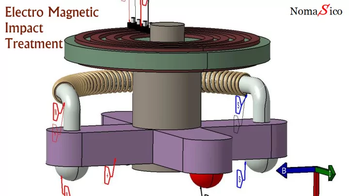
The under treatment material is coated by a thin insulating film, which in turn is covered by a conductor. Passing pulsed current through the under treatment material and the conductor results in tensile or compressive forces on the surface of the under treatment material. Auxiliary conductors may be used to control the angle (from -90 to +90 degrees with respect to the electric current conductor)
transmitting pulsed current of the proper amplitude and direction. In this way, a contactless push-pull multidirectional electromagnetic hammer is provided that can be used for impact or cyclic deformation treatment.
The said forces are proportional to the product of the applied pulsed currents and inversely proportional to the thickness of the thin insulating film. Large amount of transmitted pulsed current may result in heavy deformation of the surface of the under treatment cylinder, resulting even in polishing of its surface. In this case, the applied forces are applied due to the short gap between the under treatment cylinder and the surrounding tube. An under treatment metallic cylinder is covered by a thin insulating film (2), which in turn is covered by a surrounding metallic tube (7). the cylinder (6) is treated by means of tensile or compressive forces, vertical to its surface, by passing pulsed current through its body as well as through the surrounding metallic tube (7).
Specific Area coverage Point focused coverage
Similar treatment can be also provided in non-conducting materials by means of covering them with conducting elements. In this case, only compressive stresses can be applied on the surface of the under treatment material. Another implementation of the invention will be the removal of on surface oxides and polishing. The difference in function is fundamental and based on the alteration of current parameters. The specified device will also serve as a Non Destructive investigator by means of generating much smaller forces, which, instead of treating the under treatment material, generate elastic waves, their shape and size determining the stress level of the corresponding area of elastic wave generation, propagation and detection. Apart from that, the current use of electromagnetic forming and electromagnetic welding with inductive counter-acting response requires elevated amounts of energy to properly operate in electromagnetic forming and welding processes.
Aluminium substrate treated with ferrite layer at 2000V-150kA Aluminium substrate treated with ferrite layer at 2000V-150kA Bronze substrate treated with ferrite layer at 2000V-150kA
We have presented a new method by which non-contact push and/or pull multidirectional electromagnetic forces, applying tensile and/or compressive forces in metallic surfaces and compressive stresses in non- metallic surfaces, are able to deliver non-contact mechanical treatment including impact treatment, cyclic deformation, surface polishing, as well as contactless and efficient removal of surface oxidation, oxide removal, electromagnetic forming and electromagnetic welding, advantageously possessing the ability of adjusting the direction and the amplitude of the applied force vector.