
Development of Level-2 PSA Software AIMS-L2
Sang Hoon HAN and Jaehyun Cho Korea Atomic Energy Research Institute, 111, Daedeok-daero 989Beon-gil, Yuseong-gu, Daejeon, 305-353, Korea
*Corresponding author: shhan2@kaeri.re.kr
- 1. Introduction
KAERI has been developing software for PSA analysis, such as AIMS-PSA and FTREX for Level 1 PSA, CONPAS for Level 2 PSA. We have been using MACCS for Level 3 PSA, and we are developing a new RCAP now. CONPAS [1, 2] is software developed to analyze Level 2 PSA, and its methodology is based on the NUREG-1150 [3]. In CONPAS method, the Level 2 PSA is analyzed by receiving only the accident sequence frequency from the Level 1 PSA. Therefore, it is difficult to fully combine the Level 1 PSA and Level 2 PSA models. In addition, CONPAS software was developed with the outdated Visual Basic 6, so it can no longer be updated. KAERI decided to develop a new Level 2 PSA software AIMS-L2 that includes the following features to solve these shortcomings;
- Develop with the latest VB.net
- Management of Level 2 PSA using a project
explorer
- Ability to convert Level 2 PSA model into a fault
tree, which is required for combining Level 1 & 2 PSA models
- Ability to perform easy sensitivity analysis
- Uncertainty analysis based on the distribution of
each variable AIMS-L2 introduces the concept of project explorer, which provides an easy interface for analyzing the Level 2 PSA. The basic function of AIMS-L2 is presented in section 2. Meanwhile, various approaches for integrating Level 1 and 2 PSAs have been developed [4, 5]. AIMS-L2 provides the basis for combining Level 1 and 2 PSA models by converting the existing Level 2 PSA model
- f CONPAS into a fault tree without modifying the
Level 2 PSA model. That is, as in a typical Level 1 PSA, we can generate a model in the form of a fault tree and calculate minimal cut sets. It is described in section 3. In addition, by introducing a feature to input relations between DET events, it provides a basis that can easily analyze sensitivity and uncertainty. The features are described in section 4.
- 2. Basic Features of AIMS-L2
Loss of Feedwater Aux Feedwater Feed & Bleed Long Term DHR LOFW AFWS F&B LTDHR Seq# State 1
- k
2 cd 3
- k
4 cd 5 cd
- 1. Level-1 ET (CD)
- 2. PDS ET
Loss of Feedwater Contt' Isolation Aux Feedwater Feed & Bleed Long Term DHR Low Pressure Safety Injection Containment Spray LOFW CIS AFWS F&B LTDHR LPI/LPR CSI Seq# State 1
- k
2 1 3 2 4 3 5 4 6
- k
7 5 8 6 9 7 10 8 11 9 12 10 13 11 14 12 15
NOT ISOLATED SLOW SBO FAST SBO TRANSIENT LLOCA M/S LOCA ISOLATED RBCM GP-NO_BYPASS GP-EVENT_V GP-SGTR G-CDF-LOGIC ENTRY FROM LEVEL1 PDS ET CONTAINMENT BYPASS CONTAINMENT ISOLATION STATUS SBO. TRANSIENT OR LOCA TYPE CRITERIA CONBYPASS CONISOLAT TRANLOCA Seq# State 1 2 3 4 5 6 7 8 9
- 3. PDS Logic Diagram
C-MS-MELTSTOP C-CR-HIGH C-CR-MEDIUM C-CR-LOW C-AP-NOALPHA C-AP-ALPHA C-MS-RV_RUPTURE C-MS-CMT_FAIL C-RF-NoRCSFail C-MS-MELTSTOP Low C-AP-NOALPHA C-AP-ALPHA C-MS-RV_RUPTURE C-MS-CMT_FAIL C-RF-HLB C-RF-SGTR G-PDS-Logic CET Logic Mode of Induced Primary System Failure at RV Failure Core Melt Progressin Stopped Before RV Failure Alpha Mode Containment Failure (Steam Explosion) Amount of Corium Ejected
- ut of Cavity
CET-ET RCSFAIL MELTSTOP ALPHA CR_EJECT Seq# State 1 2 3 4 5 6 7 8 9 10 11
DET
No RCS Failure D-RCS-P-NotHigh D-NoRCSFail-Flood D-HLB-Flood D-SGTR-Flood D-CAV-Flood D-NoRCSFail-NotFlood D-HLB-NotFlood D-SGTR-NotFlood D-CAV-NotFlood D-RCS-P-High %CRITERIA RCS Fail Criteria RCS Pressure during Core Melt Progression Status of In_Cavity Injection Mode of Induced Primary System Failure D-RCSFail P-RCS CAVCOND RCSFAIL Seq# State 1 2 3 4 5 6 7 D-NoAlpha-P_NotLow D-Alpha-P_NotLow D-RCS-P-NotLow D-NoAlpha-P_Low D-Alpha-P_Low D-RCS-P-Low %CRITERIA Alpha DET RCS Pressure before Vessel Breach Alpha Mode Containment Failure D-Alpha RCSPRESS ALPHA Seq# State 1 2 3 4- 4. CET
IF P:RCSPRESS=HIGH; THEN HIGH; IF P:RCSPRESS !=HIGH; THEN NOT HIGH;
If-Then-Else rule
IF A:GISLOCA= FAILURE; THEN EVENT V; IF A:GSGTR = FAILURE; THEN SGTR; DEFAULT NO BYPASS;
If-Then-Else rule
System for PDS
S-MS-MetlStop S-MS-RV_Rupture S-MS-CB_Fail S-CI-Isolated S-CI-NotIso_CSR-Yes S-CI-NotIso_CSR-No S-CB-NoBypass S-CB-V S-CB-SGTR Source Term Catagorization Logic Diagram Contt' Bypass Contt' Isolation State Core Melt Stop before RV Rupture STC CONBYPASS CONISOLAT MELTSTOP Seq# State 1 2 3 4 5 6 7
- 5. STC
IF C:ALPHA = NO ALPHA; THEN NO ALPHA CF; IF C:ALPHA = ALPHA; THEN ALPHA CF;
If-Then-Else rule
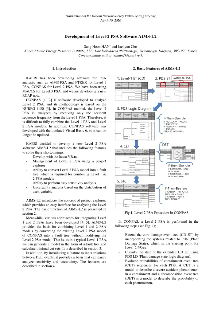
Fig 1. Level 2 PSA Procedure in CONPAS In CONPAS, a Level-2 PSA is performed in the following steps (see Fig. 1);
- Extend the core damage event tree (CD ET) by
incorporating the systems related to PDS (Plant Damage State), which is the starting point for Level-2 PSAs.
- Classify the state of the extended CD ET using
PDS LD (Plant damage state logic diagram).
- Evaluate probabilities of containment event tree