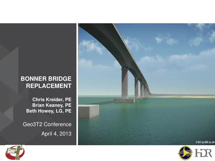

BONNER BRIDGE REPLACEMENT Chris Kreider, PE Brian Keaney, PE Beth Howey, LG, PE Geo3T2 Conference April 4, 2013
BONNER BRIDGE TIMELINE
October 1991 October 1990 June 1996 October 1993
Existing Bridge’s Navigation Span
This inlet didn’t exist before Irene struck in August of 2011
PROJECT WENT DESIGN BUILD ROUTE ► Design Build Team of PCL and HDR submitted proposal and winning bid in July, 2011 ► Winning Bid was $215,777,000.00
SUPPLEMENTAL BORINGS OBTAINED
SUBSURFACE CONDITIONS AT OREGON INLET ► Boring near each of the 83 Bents ► Colored profile based on soil type and added design scour line ► Provided soil parameters specific for each bent
SHIP IMPACT WAS A SIGNIFICANT CONCERN ► Bridge Closed October 26, 1990 ► Re-opened February 12, 1991
SCOUR WAS A HUGE CHALLENGE ► Design Scour to Elevation -84 ► Physical model scour tests performed by OEI ► Conservative design values
DIFFERENT SCOUR CONDITIONS MODELED ► Different scour conditions were evaluated at each bent to determine the critical condition for various loading scenarios. ► FBMP program utilized for each scour and loading condition. Soil at EL = 0.0 ft Long Term Scour 100-yr Scour
TWO FOUNDATION ELEMENTS USED ► 36” Prestressed Concrete Square Piles ► 532 Piles Totaling 12 Miles in Length! ► Used under large footings constructed at the water surface in navigation and transition zones ► Installed in battered configuration for increased bent stability ► 6 to 30 piles under each footing ► Maximum Factored Axial Loads ranged from 638k to 1080k for the 36 inch piles
TWO FOUNDATION ELEMENTS USED ► 54” Prestressed Concrete Cylinder Piles ► 137 Cylinder Piles totaling 3.4 Miles in Length! ► Installed in approaches where scour and ship impact are significantly less ► Piles extend all the way up to the bent caps ► 3 or 4 piles support each cap ► Maximum Factored Axial Loads for the 54” piles ranged from 751k to 1490k
LOAD TEST PROGRAM PERFORMED IN NAVIGATION ZONE ► Near proposed Bent 24 ► Deepest scour area ► Deepest water depth
JETTING TO INSTALL PILES ► PCL developed innovative jetting system ► Jet frame surrounds pile
CLOSE UP OF JETTING PORTS ► Jet ports direct water and air toward pile to limit disturbance to surrounding soil ► Important because 36” square piles are only 7.5 feet apart
Jet in action with water and air
LARGE HAMMER REQUIRED! ► Delmag D-225 Ram Weight = ► 49.6 kips ► Maximum Rated Energy = 565 kip- feet Weighs 200 kips! ► ► After jetting to near the final tip elevation, piles are driven to extend below potential disturbed zone beneath the tip ► Pile driving also helps verify adequate resistance has been achieved
LOAD TEST IN PROGRESS
LARGE HAMMER REQUIRED! ► After jetting to near the final tip elevation, piles are driven to extend below potential disturbed zone beneath the tip ► Pile driving also helps verify adequate resistance has been achieved
Recommend
More recommend