
4
Network Layer Network Layer
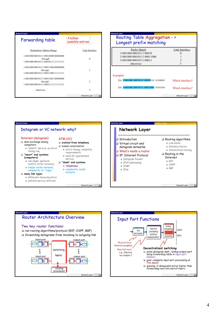
Forwarding table
Destination Address Range Link Interface 11001000 00010111 00010000 00000000 through 11001000 00010111 00010111 11111111 11001000 00010111 00011000 00000000 through 1 11001000 00010111 00011000 11111111 11001000 00010111 00011001 00000000 through 2 11001000 00010111 00011111 11111111
- therwise
3
4 billion possible entries
Network Layer
19
Network Layer Network Layer
Routing Table Aggregation - > Longest prefix matching
Prefix Match Link Interface 11001000 00010111 00010 11001000 00010111 00011000 1 11001000 00010111 00011 2
- therwise
3
DA: 11001000 00010111 00011000 10101010
Examples
DA: 11001000 00010111 00010110 10100001
Which interface? Which interface?
Network Layer
20
Network Layer Network Layer
Datagram or VC network: why?
Internet (datagram)
data exchange among
computers
“elastic” service, no strict
timing req.
“smart” end systems
(computers)
can adapt, perform
control, error recovery
simple inside network,
complexity at “edge”
many link types
different characteristics uniform service difficult
ATM (VC)
evolved from telephony human conversation:
strict timing, reliability
requirements
need for guaranteed
service
“dumb” end systems
telephones complexity inside
network
Network Layer
21
Network Layer Network Layer
Network Layer
Introduction Virtual circuit and
datagram networks
What’s inside a router IP: Internet Protocol
Datagram format IPv4 addressing ICMP IPv6
Routing algorithms
Link state Distance Vector Hierarchical routing
Routing in the
Internet
RIP OSPF BGP Inside a router Network Layer
22
Network Layer Network Layer
Router Architecture Overview
Two key router functions:
run routing algorithms/protocol (RIP, OSPF, BGP) forwarding datagrams from incoming to outgoing link
Network Layer
23
Network Layer Network Layer
Input Port Functions
Decentralized switching:
given datagram dest., lookup output port
using forwarding table in input port memory
goal: complete input port processing at
‘line speed’
queuing: if datagrams arrive faster than
forwarding rate into switch fabric Physical layer: bit-level reception Data link layer: e.g., Ethernet see chapter 5
Network Layer