
SLIDE 1
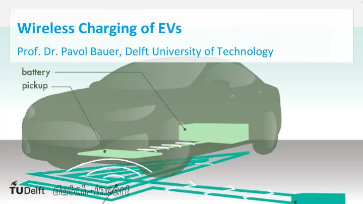
Wireless Charging of EVs
- Prof. Dr. Pavol Bauer, Delft University of Technology
Wireless Charging of EVs Prof. Dr. Pavol Bauer, Delft University of - - PowerPoint PPT Presentation
Wireless Charging of EVs Prof. Dr. Pavol Bauer, Delft University of Technology Learning objectives 1. What are the advantages and disadvantages of wireless charging? 2. What are the parts of an inductive wireless charging system? 3. How does
Image source: Plugless power
M DC DC DC AC DC /Rectified DC Input Inverter Primary Compensation Secondary Compensation Rectifier Regulator Traction motor Battery Electric Vehicle DC AC
Copper conductor Al shield Ferrite bars
C1 C2 I2 L1-M L2-M M I’1 E2 +
RL,eq
Equivalent load circuit model
V1
M DC DC DC AC DC /Rectified DC i/p VLF-LF Inverter Primary Compensation Secondary Compensation Rectifier Regulator Traction motor Battery Electric Vehicle
C1 C2 I2 L1-M L2-M M I’1 E2 +
RL,eq
Equivalent load circuit model
V1
"
"#" cos θ
"
"#′"
C1 C2 I2 L1-M L2-M M I’1 E2 +
RL,eq V1 I2 L1-M L2-M M I1 E2 +
RL,eq V1