Outline Introduction Paper: Paper: Why DRA Types of DRA - - PowerPoint PPT Presentation

outline
SMART_READER_LITE
LIVE PREVIEW

Outline Introduction Paper: Paper: Why DRA Types of DRA - - PowerPoint PPT Presentation

Paper presentation Ultra-Portable Devices Outline Introduction Paper: Paper: Why DRA Types of DRA elements A. Petosa, A. Ittipiboon, Y.M.M. Antar, D. Roscoe and M. Cuhaci R Recent Advances in Dielectric Resonator


slide-1
SLIDE 1

Paper presentation – Ultra-Portable Devices

Paper: Paper:

  • A. Petosa, A. Ittipiboon, Y.M.M. Antar, D. Roscoe and M. Cuhaci

”R t Ad i Di l t i R t A t ”Recent Advances in Dielectric Resonator Antenna Technology” IEEE Antennas and Propagation Magazine, Vol. 40, No. 3, June 1998

Presented by:

Rohit Chandra

2010-01-26 1 Paper Presentation - Ultra Portable Devices

Outline

  • Introduction
  • Why DRA
  • Types of DRA elements
  • Array configuration
  • Summary

2010-01-26 2 Paper Presentation - Ultra Portable Devices

Introduction

  • Is DRA alternative to traditional Antenna?
  • Past work done to characterize basic properties of DRA for

variety of simple shapes and feed configuration

  • Recent development: novel DRA elements to enhance BW

and gain; active DRA using ferrite materials; compact and low profile DRAs profile DRAs

2010-01-26 3 Paper Presentation - Ultra Portable Devices

What is DRA

  • Resonant antenna fabricated from low-loss microwave

di l t i t i l dielectric material.

  • Resonant frequency: function of size, shape, and εr
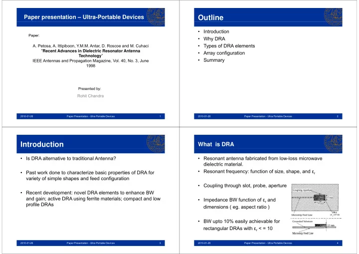
  • Coupling through slot, probe, aperture
  • Impedance BW function of εr and

dimensions ( eg. aspect ratio )

  • BW upto 10% easily achievable for

rectangular DRAs with εr < = 10

2010-01-26 4 Paper Presentation - Ultra Portable Devices

slide-2
SLIDE 2

Return Loss And Pattern for rectangular DRA rectangular DRA Why DRA

  • Radiation Efficiency > 95%
  • Various shapes: flexibility in design
  • Several feeding mechanisms: capable to integrate with various technologies
  • Various modes producing broadside or conical pattern
  • Various modes producing broadside or conical pattern
  • Wide range of εr ( 6-100): Control over size and BW ( wide BW: low εr , compact

size: high εr )

  • Low/No tolerance errors
  • Enhancing techniques for MPA equally applicable for DRA

Types of DRA element

  • Wide band DRA
  • Compact
  • Circular Polarized
  • High Gain
  • Active

Wideband DRA

  • Notched rectangular DRA
  • slot fed
  • notch decreases radiation

Q factor increases BW

  • Dimension of Notch can be

adjusted for Dual Mode or wideband operations.

slide-3
SLIDE 3

Wideband DRA

M lti t DRA

  • Multi-segment DRA
  • Strong Coupling: High εr
  • Wide bandwidth: Low εr
  • To Resolve : High εr inserted below

g

r

Low εr for matching impedance of DRA

  • BW 20 %

Wideband DRA

P iti DRA

  • Parasitic DRAs
  • Same technique as used in MPA
  • Parasitic DRA resonates as different

frequency

  • Combined effect produces wideband

individual BW:5.8%, combined:17%

  • Single Feed, No matching Network,

multiband operation also possible

Compact DRA

F h lf V l i t 8 ti

  • Frequency half Volume increment 8 times
  • Increase εr BW decreases
  • Solution : Placing Short-circuit at point of symmetry in E-fields
  • Some decrease in BW but can be increased by MSDRA
  • Some decrease in BW but can be increased by MSDRA

Circular Polarization

  • Complexity in design of CP radiation
  • two point feed: equal amplitude in phase quadrature

i d di id i i i i l required power divider: increase in insertion loss

  • single feed: redesigning MPA’s patch for

d l th l d

  • d

N BW ( 1 2 %) dual-orthogonal modes produces Narrow BW ( 1-2 %)

  • For DRA single feed upto 7% BW
slide-4
SLIDE 4

High Gain DRA Active DRAs :FRAs

  • When unbiased: FRAs similar to DRAs
  • Biasing: parameters can be controlled electronically:

can shift frequency either above or below depending q y p g upon direction of bias field

Array Configuration

  • Series fed array
  • Series fed array

Disadvantage:

  • can’t be used for wide-band fixed beam

can t be used for wide band fixed beam applications

  • small amount of coupling b/w microstrip and

p g p DRA Solution ( in same space constraint):

  • branch line feed
  • MSDRAs

Planar Arrays

slide-5
SLIDE 5

Summary

  • DRAs can be used as an alternative to traditional antennas for

several cases

  • Flexibility in design
  • Compact and low cost