
SLIDE 1
Programmable Logic Devices Verilog State Machines CMPE 415 1 (10/16/07)
UMBC
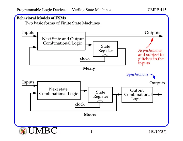
U M B C U N I V E R S I T Y O F M A R Y L A N D B A L T I M O R E C O U N T Y 1 9 6 6Behavioral Models of FSMs Two basic forms of Finite State Machines Inputs Next State and Output Combinational Logic State Register Outputs clock Mealy Inputs Next state Combinational Logic State Register clock Moore Output Combinational Logic Outputs Asynchronous and subject to glitches in the inputs Synchronous