
SLIDE 1
1 DSP-4100 vs. The Competition August 2000
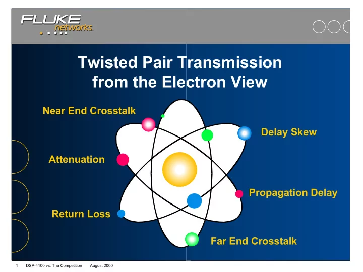
Twisted Pair Transmission from the Electron View Near End Crosstalk - - PowerPoint PPT Presentation
Twisted Pair Transmission from the Electron View Near End Crosstalk Delay Skew Attenuation Propagation Delay Return Loss Far End Crosstalk 1 DSP-4100 vs. The Competition August 2000 Traveling Down the Copper Highway A
1 DSP-4100 vs. The Competition August 2000
2 DSP-4100 vs. The Competition August 2000
3 DSP-4100 vs. The Competition August 2000
4 DSP-4100 vs. The Competition August 2000
5 DSP-4100 vs. The Competition August 2000
6 DSP-4100 vs. The Competition August 2000
7 DSP-4100 vs. The Competition August 2000
8 DSP-4100 vs. The Competition August 2000
9 DSP-4100 vs. The Competition August 2000
10 DSP-4100 vs. The Competition August 2000
11 DSP-4100 vs. The Competition August 2000
12 DSP-4100 vs. The Competition August 2000
13 DSP-4100 vs. The Competition August 2000
14 DSP-4100 vs. The Competition August 2000
15 DSP-4100 vs. The Competition August 2000
16 DSP-4100 vs. The Competition August 2000
17 DSP-4100 vs. The Competition August 2000
18 DSP-4100 vs. The Competition August 2000
19 DSP-4100 vs. The Competition August 2000
20 DSP-4100 vs. The Competition August 2000
21 DSP-4100 vs. The Competition August 2000
22 DSP-4100 vs. The Competition August 2000