Consideration of Vertical Field-of-View of the Camera for Video Alarm - - PDF document

β–Ά
consideration of vertical field of view of the camera for
SMART_READER_LITE
LIVE PREVIEW

Consideration of Vertical Field-of-View of the Camera for Video Alarm - - PDF document

Transactions of the Korean Nuclear Society Virtual Spring Meeting July 9-10, 2020 Consideration of Vertical Field-of-View of the Camera for Video Alarm Assessment Hyun-Chul KIM and Byung-Woo SHIN 1418 Yuseong-daero, Yuseong-gu, Daejeon, Republic


slide-1
SLIDE 1

Transactions of the Korean Nuclear Society Virtual Spring Meeting July 9-10, 2020

Consideration of Vertical Field-of-View of the Camera for Video Alarm Assessment

Hyun-Chul KIM and Byung-Woo SHIN 1418 Yuseong-daero, Yuseong-gu, Daejeon, Republic of Korea hckim@kinac.re.kr, sbw97@kinac.re.kr

  • 1. Introduction

Detection, delay and response are key functions of an effective physical protection system(PPS). Detection is a PPS process that begins with sensing an intrusion and an alarm being raised [1, 2]. Alarm assessment completes the detection function by assessing the cause of the alarm. It includes deciding whether the alarm is caused by adversary or not. Typical method of alarm assessment is video alarm assessment though the video coverage of each sensor detection zone (called the assessment zone when sensor and video are integrated) [3]. The alarm assessment zone for each security camera is the volume of space where the bottom is on the ground and has the dimension of the zone width and the zone

  • length. For the perimeter assessment zone, the zone

width is determined as the width of the isolation zone between two perimeter fences. Regarding the zone length, the assessment zone is required to be located within the region between the zone width near-field-of- view(NFOV) distance and resolution-limited far-field-

  • f-view(FFOV) distance [4, 5]. Those distances are

dependent on the specification and configuration of the camera. The international and regional training courses hosted by the International Atomic Energy Agency include a subgroup exercise to calculate of the zone width NFOV and resolution-limited FFOV distances for the given camera specification [3]. However, the equations used in the training courses consider only the horizontal field-of- view(FOV) but not the vertical FOV. This paper presents revised equations to calculate the zone width NFOV and resolution-limited FFOV distances as well as additional requirements, taking the vertical FOV into account.

  • 2. Previously Known Method

The formula for calculating FOV distance (D) from the camera is given as D = πΌπΊπ‘ƒπ‘Š 𝐺

𝑀

𝑋

𝐽

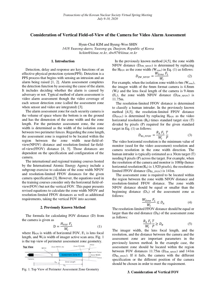
(1) where HFOV is width of horizontal FOV, FL is lens focal length, and WI is width of imager active scan area. Fig. 1 is the top view of perimeter assessment zone geometry.

  • Fig. 1. Top View of Perimeter Assessment Zone Geometry

In the previously known method [4,5], the zone width NFOV distance (DZW_NFOV) is determined by replacing the HFOV as the zone width (Wzone) in Eq. (1) as follows: πΈπ‘Žπ‘‹_π‘‚πΊπ‘ƒπ‘Š = 𝑋

π‘Žπ‘π‘œπ‘“ 𝐺 𝑀

𝑋

𝐽

(2) For example, when the isolation zone width is 6m (Wzone), the imager width of the 6mm format camera is 4.8mm (WI) and the lens focal length of the camera is 9.4mm (FL), the zone width NFOV distance (DZW_NFOV) is 11.75m. The resolution-limited FFOV distance is determined to classify a human intruder. In the previously known method [4,5], the resolution-limited FFOV distance (DFFOV) is determined by replacing HFOV as the video horizontal resolution (Rh) times standard target size (T) divided by pixels (P) required for the given standard target in Eq. (1) as follows: 𝐸𝑆𝑀_πΊπΊπ‘ƒπ‘Š = π‘†β„Ž 𝐺

𝑀

𝑋

𝐽

π‘ˆ 𝑄 (3) The video horizontal resolution is the minimum value of monitor (used for the video assessment) resolution and camera resolution in the zone width direction. The human intruder is typically estimated as a 30cm target (T) needing 8 pixels (P) across the target. For example, when the resolution of the camera and monitor is 1080p (hence horizontal resolution(Rh) is 1,920 pixels), the resolution- limited FFOV distance (DRL_FFOV) is 141m. The assessment zone is required to be located within the region between the zone width NFOV distance and resolution-limited FFOV distance. The zone width NFOV distance should be equal or smaller than the beginning distance (DA) of the assessment zone as follows: 𝑋

π‘Žπ‘π‘œπ‘“ 𝐺 𝑀

𝑋

𝐽

≀ 𝐸𝐡 (4) The resolution-limited FFOV distance should be equal or larger than the end distance (DB) of the assessment zone as follows: π‘†β„Ž 𝐺

𝑀

𝑋

𝐽

π‘ˆ 𝑄 β‰₯ 𝐸𝐢 (5) The imager width, the lens focal length, and the resolution, and the distance between the camera and the assessment zone are important parameters in the previously known method. In the example case, the assessment zone should be located within the region between FOV distances 11.75m (DZW_NFOV) and 141m (DRL_FFOV). If it fails, the camera with the different specification or the different position of the camera should be chosen in order to meet the requirement.

  • 3. Consideration of Vertical FOV
slide-2
SLIDE 2

Transactions of the Korean Nuclear Society Virtual Spring Meeting July 9-10, 2020

When the zone width NFOV and resolution-limited FFOV distances are calculated in the previously known method, only the horizontal FOV is considered but not the vertical FOV. Fig. 2 is the top and side views and the monitor view of perimeter assessment zone geometry.

  • Fig. 2. Top and Side Views of Perimeter Assessment Zone

Geometry

The half angle of vertical view (ΞΈvh) can calculated as πœ„π‘€β„Ž = tanβˆ’1 𝑋

𝐼

2𝐺

𝑀

(6) where WH is height of imager active scan area. In the example case, the imager height of the 6mm format camera is 3.6mm and hence the half angle of vertical view (ΞΈvh) is 10.84Β°. When the vertical FOV is taken into account, the zone width NFOV distance (DZW_NFOV) should be corrected from Eq. (2) as follows: πΈπ‘Žπ‘‹_π‘‚πΊπ‘ƒπ‘Š = 𝑋

π‘Žπ‘π‘œπ‘“ 𝐺 𝑀

𝑋

𝐽

sin πœ„π‘Žπ‘‹ (7) where ΞΈzw is the vertical angle of zone width NFOV. Since the vertical angle of zone width NFOV is larger than the vertical mounting angle (ΞΈm) minus the half angle of vertical view (ΞΈvh), Eq. (7) combined with Eq. (4) becomes 𝑋

π‘Žπ‘π‘œπ‘“ 𝐺 𝑀

𝑋

𝐽

sin(πœ„π‘› βˆ’ πœ„π‘€β„Ž) < 𝐸𝐡 (8) It is less stringent requirement compared to the previously known method since Eq. (8) is met whenever

  • Eq. (4) is met. In the example case, the beginning

distance (DA) of the assessment zone should be larger than 11.75m times sin(ΞΈm – 10.84Β°). The resolution-limited FFOV distance (DRL_FFOV) should be corrected from Eq. (3) as follows: 𝐸𝑆𝑀_πΊπΊπ‘ƒπ‘Š = π‘†β„Ž 𝐺

𝑀

𝑋

𝐽

π‘ˆ 𝑄 sinπœ„π‘†π‘€ (9) where ΞΈRL is the vertical angle of resolution-limited

  • FFOV. Since the vertical angle of resolution-limited

FFOV is smaller than the vertical mounting angle (ΞΈm) plus the half angle of vertical view (ΞΈvh), Eq. (9) combined with Eq. (5) becomes π‘†β„Ž 𝐺

𝑀

𝑋

𝐽

π‘ˆ 𝑄 sin(πœ„π‘› + πœ„π‘€β„Ž) > 𝐸𝐢 (10) It is more stringent requirement compared to the previously known method since Eq. (5) is met whenever

  • Eq. (10) is met. In the example case, the end distance (DB)
  • f the assessment zone should be smaller than 141m

times sin(ΞΈm + 10.84Β°). The assessment zone is required to be located within the region between the zone width NFOV distance and resolution-limited FFOV distance. In the previously known method, it is required that Eqs. (4) and (5) are met. Meanwhile, when the vertical FOV is taken into account, it is required that Eqs. (8) and (10) are met instead. Compared to the previously known method, additional parameters such as the imager height and the vertical mounting angle are involved. When the vertical FOV is taken into account, there are two additional requirements to be met. First of all, in

  • rder that the camera view should cover the entire region
  • f assessment zone, the following conditions should be

met. tan(πœ„π‘› + πœ„π‘€β„Ž) β‰₯ 𝐸𝐢 𝐼 (11) tan(πœ„π‘› βˆ’ πœ„π‘€β„Ž) ≀ 𝐸𝐡 𝐼 (12) where H is the camera mounting height. For example, when the camera is mounted at the height of 8m (H), the beginning distance (DA) of the assessment zone should be equal or larger than 8m times tan(ΞΈm-10.84Β°) and the end distance (DB) should be equal or smaller than 8m times tan(ΞΈm+10.84Β°). The other requirement is that the horizon is not in the FOV in order to reduce the glare at sunrise and sunset. Consequently, the following condition should be met. πœ„π‘› + πœ„π‘€β„Ž < 90Β° (13) Compared to the previously known method, additional parameters such as the imager height, the vertical mounting angle, and the camera mounting height are

  • involved. In the example case, the vertical mounting

angle (ΞΈm) should be less than 79.16Β°. For example, when the camera is positioned so that the beginning and end distances of the assessment zone from the camera are 64 m (DA) and 128m (DB), Eq. (10) requires the vertical mounting angle (ΞΈm) to be larger than 54.36Β° while Eqs. (11) and (12) require the vertical mounting angle to be between the range of 75.58Β° and 93.71Β°. Finally, taking all the equations (including Eq. (13)) into account, the vertical mounting angle (ΞΈm) should be equal or larger than 75.58Β° and smaller than 79.16Β°. If no range of the vertical mounting angle exists unlike the example case, the camera with the different specification or the different configuration of the camera should be chosen in order to meet the requirement.

  • 4. Conclusions

This paper presented revised equations (Eqs. (8) and (10)) to calculate the zone width NFOV and resolution- limited FFOV distances as well as additional requirements (Eqs. (11) to (13)), taking the vertical FOV into account. As a result, it is learnt that additional parameters such as the imager height, the vertical mounting angle, and the camera mounting height are

  • involved. It is highlighted that the equations above are

useful particularly when planning the installation of new

  • cameras. The vertical mounting angle can be used as the
slide-3
SLIDE 3

Transactions of the Korean Nuclear Society Virtual Spring Meeting July 9-10, 2020

variable since it is easy to be changed in comparison to

  • ther parameters even after the installation. If no range
  • f the vertical mounting angle to meet the equations

above exists, the camera with the different specification

  • r the different configuration of the camera should be

chosen. REFERENCES

[1] IAEA Nuclear Security Series No. 27-G, β€œPhysical Protection of Nuclear Material and Nuclear Facilities (Implementation of INFCIRC/225/Revision 5)”, IAEA, Vienna, 2018. [2] IAEA NST055, β€œHandbook on the Design of Physical Protection Systems for Nuclear Material and Nuclear Facilities”, IAEA, Vienna, to be published. [3] Mary Lynn Garcia, β€œVulnerability Assessment of Physical Protection Systems”, Elsevier Butterworth-Heinemann, 2006. [4] Mary Lynn Garcia, β€œThe Design and Evaluation of physical Protection Systems”, Butterworth-Heinemann, 2008. [5] Supplemental Material of 28th International Training Course on the Physical Protection Nuclear Material and Nuclear Facilities, U.S. Sandia National Laboratory, 2019.