signal types
play

Signal Types Recall even digital signals are just - PowerPoint PPT Presentation

1 2 Signal Types Recall even digital signals are just ___________________ Analog signal Continuous time signal where each voltage level has a unique meaning EE 109 Unit 18 Noise Margins, Digital signal Continuous


  1. 1 2 Signal Types • Recall even digital signals are just ___________________ … • Analog signal – Continuous time signal where each voltage level has a unique meaning EE 109 Unit 18 – Noise Margins, • Digital signal – Continuous signal where voltage levels are mapped into ____ ranges Interfacing, and Tri-States meaning 0 or 1 volts volts 1 1 Threshold 0 0 0 time time Analog Digital 3 4 Signals and Meaning Analog Digital 5.0 V 5.0 V Logic 1 2.0 V Illegal Threshold Range 0.8 V NOISE MARGINS, LEVEL SHIFTERS, Logic 0 & DRIVE STRENGTH 0.0 V 0.0 V Each voltage value Each voltage maps to ‘0’ or ‘1’ has unique meaning (There is a small illegal range where meaning is undefined since threshold can vary based on temperature, small variations in manufacturing, etc.)

  2. 5 6 A Motivating Example 
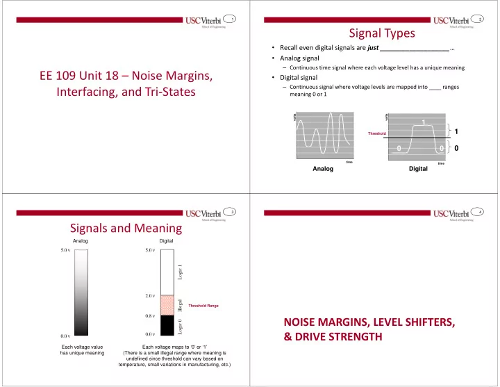
The Digital Abstraction • Digital is a nice abstraction of voltage and current – Lets us just think 'on' or 'off' but not really worry about the voltages and Example 1 Example 2 currents underneath • You connect an output port to an LED • You have correctly built a circuit • ______________________!!! (light emitting diode) and connect using chips provided by your everything correctly . The light should • Not all 1's and 0's are _____________________ instructor and verified its outputs turn on when you set your output bit to You then attempt to interface it – A '1' can be any 'HIGH' voltage (maybe in the range _______________) • a high voltage (logic '1'). to a specific microprocessor – A '0' can be any 'LOW' voltage (maybe in the range _______________) • When you turn the system on the LED • When you connect them the does not glow. You measure the – So 3V and 5V both mean _______ but they aren't equal voltage at the gate output with a microprocessor indicates that it • Similarly certain outputs of a chip may connect to other devices voltmeter and find it is not 5V but never senses your circuit that require more _________ than the output can ____________ 2.3V? Why isn't it a logic 1? producing logic '1'. Why? • The ___________________ output – Think of connecting a fire hose to your _________________ • Different circuit implementation ability from the output port is not ____ techniques use different _______ – Or even worse your _____________ to a fire hydrant…it would ________ it enough to adequately _______ the LED __________ to indicate '1' or '0' – In the same way, inputs and outputs of different devices must be matched to which then drags the voltage ______. and may be _________________ the ______________________________ of what they connect to Lesson To Be Learned: Not all 1's or 0's are created equal! 7 8 Digital Voltage Noise Margins Class Activity • Consider one digital gate feeding another OH = Output High OL = Output Low IH = Input High • Do an internet search for "74LS00 datasheet" IL = Input Low NM = Noise Margin (this is a chip w/ some 2-input NAND gates) ________ Range ________ Range and try to find any PDF and open it Interpretation Interpretation 5.0 V 5.0 V • Skim the PDF and try to find: NM H = Logic 1 Logic 1 V OH As long as ______ – VOH, VIH, VOL, VIL _____________ and _____________ we are in good shape… V IH Electromagnetic interference & power Illegal Illegal spikes can cause this to break down V IL Logic 0 Logic 0 V OL NM L = 0.0 V 0.0 V ______

  3. 9 10 Analogy Current Limitations • When a circuit outputs a 'HIGH' ('1') it can only supply ( ___________) so much current (think of your garden hose spigot) = ___________ • Consider a sprinkler system…what will happen if you add 100 • When a circuit outputs a 'LOW' ('0') it can only suck up ( _________) so new sprinklers to your backyard? much current = __________ • Pressure (voltage) will go __________ and _____________ • When a circuit receives a 'HIGH' signal on the input side it may need a water (current) flow coming out of each certain amount of current to recognize the input as 'HIGH' = _______ • When a circuit receives a 'LOW' signal on the input side it may need a certain amount of current to recognize the input as 'LOW' = _______ I IH I IL 1 0 I OH I OL 11 12 Consideration All In the Family • If we attach too many gates to one output it • There are many families of circuit devices that talk different may not be enough to drive those gates language (Each has a different VOH, VIH, VOL, VIL, IOL, IIL, etc.) • Need to make sure the current • Examples: requirements and capabilities match – ______________ • Let's say we connect one of the NAND gates – ______________ on the 74LS00 chip to an input of N other – ______________ If I OH or I OL is too _______ we NAND gates… can split the loads by place • Must make sure if you interface two different devices that they intermediate buffers • Can it produce/suck up the required are _______________ (i.e. VOH of device A is greater than VIH current… of device B) or use a buffer/amplifier/level shifter circuit to help • …if N = 6? them talk to each other – http://www.ti.com/lit/ds/symlink/cd4504b-ep.pdf • …if N = 12? VOH=2.2V VIH=3.5V A B

  4. 13 14 Arduino Limits Another Example • Now consider a speaker system where the power and signal • Arduino outputs can sink (suck up) and source (produce) are provide together around a maximum of 20 mA on a pin – Given our Arduino use 5V = Vcc and its current limitations per pin, how – http://www.atmel.com/Images/Atmel-8271-8-bit-AVR- much power can we supply to the speaker? Microcontroller-ATmega48A-48PA-88A-88PA-168A-168PA-328- 328P_datasheet.pdf – 5V * _____________ = ___________ • Do an internet search for "Standard Servo Motor Datasheet" – You ___________ an amplifier… and find the maximum current it may need Power & Signal • It doesn't seem like the Arduino would be together able to drive the servo motor. How is it working? – Remember the 3-pin interface: R = Power, B = Ground, W = Signal – The signal is __________ from the power – The power source is used to amplify the signal 15 16 Typical Logic Gate Hot Water = Logic 1 • Gates can output two values: 0 & 1 Cold Water = Logic 0 – Logic ‘1’ (Vdd = 3V or 5V), or Logic ‘0’ (Vss = GND) (Strapped together so always one type – But they are ALWAYS outputting something!!! of water coming out) • Analogy: a sink faucet – 2 possibilities: Hot (‘1’) or Cold (‘0’) • In a real circuit, inputs cause EITHER a pathway from output to VDD OR VSS ��� ��� Inputs Vdd PMOS PMOS TRI-STATE GATES Inputs Inputs Output Output NMOS NMOS Vss

  5. 17 18 Output Connections Tri-State Buffers ��� • Can we connect the output of two logic gates together? • Normal digital gates can output two • ______! Possible _______________ (static, low-resistance values: 0 & 1 PMOS pathway from Vdd to GND) 1. Logic 0 = 0 volts Inputs Output • We call this situation _______________________ 2. Logic 1 = 5 volts Z (high • Tristate buffers can output a third Inputs impedance) Vdd NMOS value: Src 1 3. __ = _____________________ = "Floating" Src 1 (no connection to any voltage source…__________________ resistance) Vss Src 2 • Analogy: a sink faucet Inputs Vdd – 3 possibilities: 1.) Hot water, Hot Water = Logic 1 Src 2 2.) Cold water, Src 3 Cold Water = Logic 0 3.) ________ water ___ Water = Z (High-Impedance) Vss 19 20 Tri-State Buffers Tri-State Buffers • We use tri-state buffers to _________ one output • Tri-state buffers have an extra Tri-State Buffer enable input amongst several sources • When disabled, output is said In Out = In • Rule: Only ______________________ at a time E to be at high impedance (a.k.a. Z) Src 1 Enable=1 E – High Impedance is equivalent to no connection (i.e. floating EN1 In Out = ____ output) or an infinite resistance E Src 2 D Q – It's like a brick wall between the E D-FF output and any connection to Enable=0 EN2 source Q CLK En In Out • When enabled, normal buffer Src 3 0 - Z E 1 0 0 EN3 1 1 1

  6. 21 22 Tri-State Buffers Communication Connections • We use tri-state buffers to share one output amongst several • Multiple entities need to communicate sources • Rule: Only 1 buffer enabled at a time • We could use • When 1 buffer enabled, its output overpowers the Z’s (no – Point-to-point connections connection) from the other gates – A ___________________________ 0 0 output of 0 E Select source Separate point to point overpowers 1 to pass its 1 connections the Z data Shared Bus 0 1 Z D Q E D-FF 0 Q CLK 0 Z Disabled E buffers 0 output ‘Z’ 23 24 Bidirectional Bus Tri-State Gates • Big advantage: don’t have to know in advance how many devices • _____ transmitter (otherwise bus contention) will be connected together – Tri-State gates give us the option of connecting together the outputs of • N receivers many devices without requiring a circuit to multiplex many signals into one • Each device can send (though 1 at a time) or • Just have to make sure only one is enabled (output active) at any one time. receive Source w/ Tri-State Gates src1 src1 src2 src2 src3 Single output src3 MUX 0 1 0 0 srcn srcn Input Output Select Enables

Download Presentation
Download Policy: The content available on the website is offered to you 'AS IS' for your personal information and use only. It cannot be commercialized, licensed, or distributed on other websites without prior consent from the author. To download a presentation, simply click this link. If you encounter any difficulties during the download process, it's possible that the publisher has removed the file from their server.

Recommend


More recommend