
SLIDE 1
Signal Hill Professional Center:
Implementing a Concrete Structural System
Joseph Henry,Structural Option
- Dr. Linda Hanagan, Advisor
Signal Hill Professional Center: Implementing a Concrete Structural - - PowerPoint PPT Presentation
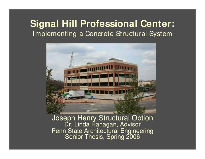
Signal Hill Professional Center: Implementing a Concrete Structural System Joseph Henry,Structural Option Dr. Linda Hanagan, Advisor Penn State Architectural Engineering Senior Thesis, Spring 2006 Building I ntroduction Design Background
JOSEPH HENRY Structural Hanagan, Advisor
JOSEPH HENRY Structural Hanagan, Advisor
JOSEPH HENRY Structural Hanagan, Advisor
JOSEPH HENRY Structural Hanagan, Advisor
JOSEPH HENRY Structural Hanagan, Advisor
JOSEPH HENRY Structural Hanagan, Advisor
JOSEPH HENRY Structural Hanagan, Advisor
JOSEPH HENRY Structural Hanagan, Advisor
JOSEPH HENRY Structural Hanagan, Advisor
JOSEPH HENRY Structural Hanagan, Advisor
JOSEPH HENRY Structural Hanagan, Advisor
JOSEPH HENRY Structural Hanagan, Advisor
JOSEPH HENRY Structural Hanagan, Advisor
JOSEPH HENRY Structural Hanagan, Advisor
JOSEPH HENRY Structural Hanagan, Advisor
JOSEPH HENRY Structural Hanagan, Advisor
JOSEPH HENRY Structural Hanagan, Advisor
JOSEPH HENRY Structural Hanagan, Advisor
JOSEPH HENRY Structural Hanagan, Advisor
JOSEPH HENRY Structural Hanagan, Advisor
JOSEPH HENRY Structural Hanagan, Advisor
JOSEPH HENRY Structural Hanagan, Advisor
JOSEPH HENRY Structural Hanagan, Advisor
JOSEPH HENRY Structural Hanagan, Advisor
JOSEPH HENRY Structural Hanagan, Advisor
JOSEPH HENRY Structural Hanagan, Advisor
JOSEPH HENRY Structural Hanagan, Advisor
JOSEPH HENRY Structural Hanagan, Advisor
JOSEPH HENRY Structural Hanagan, Advisor
JOSEPH HENRY Structural Hanagan, Advisor
JOSEPH HENRY Structural Hanagan, Advisor
JOSEPH HENRY Structural Hanagan, Advisor
JOSEPH HENRY Structural Hanagan, Advisor
JOSEPH HENRY Structural Hanagan, Advisor
JOSEPH HENRY Structural Hanagan, Advisor
JOSEPH HENRY Structural Hanagan, Advisor
JOSEPH HENRY Structural Hanagan, Advisor
JOSEPH HENRY Structural Hanagan, Advisor
JOSEPH HENRY Structural Hanagan, Advisor
JOSEPH HENRY Structural Hanagan, Advisor
JOSEPH HENRY Structural Hanagan, Advisor
JOSEPH HENRY Structural Hanagan, Advisor
JOSEPH HENRY Structural Hanagan, Advisor
JOSEPH HENRY Structural Hanagan, Advisor
JOSEPH HENRY Structural Hanagan, Advisor
JOSEPH HENRY Structural Hanagan, Advisor
JOSEPH HENRY Structural Hanagan, Advisor
JOSEPH HENRY Structural Hanagan, Advisor
JOSEPH HENRY Structural Hanagan, Advisor
JOSEPH HENRY Structural Hanagan, Advisor
JOSEPH HENRY Structural Hanagan, Advisor
JOSEPH HENRY Structural Hanagan, Advisor
JOSEPH HENRY Structural Hanagan, Advisor
JOSEPH HENRY Structural Hanagan, Advisor
JOSEPH HENRY Structural Hanagan, Advisor
JOSEPH HENRY Structural Hanagan, Advisor
JOSEPH HENRY Structural Hanagan, Advisor
JOSEPH HENRY Structural Hanagan, Advisor
JOSEPH HENRY Structural Hanagan, Advisor
JOSEPH HENRY Structural Hanagan, Advisor
JOSEPH HENRY Structural Hanagan, Advisor
JOSEPH HENRY Structural Hanagan, Advisor
JOSEPH HENRY Structural Hanagan, Advisor
JOSEPH HENRY Structural Hanagan, Advisor
JOSEPH HENRY Structural Hanagan, Advisor
JOSEPH HENRY Structural Hanagan, Advisor
JOSEPH HENRY Structural Hanagan, Advisor
JOSEPH HENRY Structural Hanagan, Advisor
JOSEPH HENRY Structural Hanagan, Advisor
JOSEPH HENRY Structural Hanagan, Advisor
JOSEPH HENRY Structural Hanagan, Advisor
JOSEPH HENRY Structural Hanagan, Advisor
JOSEPH HENRY Structural Hanagan, Advisor
JOSEPH HENRY Structural Hanagan, Advisor
JOSEPH HENRY Structural Hanagan, Advisor
JOSEPH HENRY Structural Hanagan, Advisor
JOSEPH HENRY Structural Hanagan, Advisor
JOSEPH HENRY Structural Hanagan, Advisor
JOSEPH HENRY Structural Hanagan, Advisor
JOSEPH HENRY Structural Hanagan, Advisor
JOSEPH HENRY Structural Hanagan, Advisor
JOSEPH HENRY Structural Hanagan, Advisor