
SLIDE 1
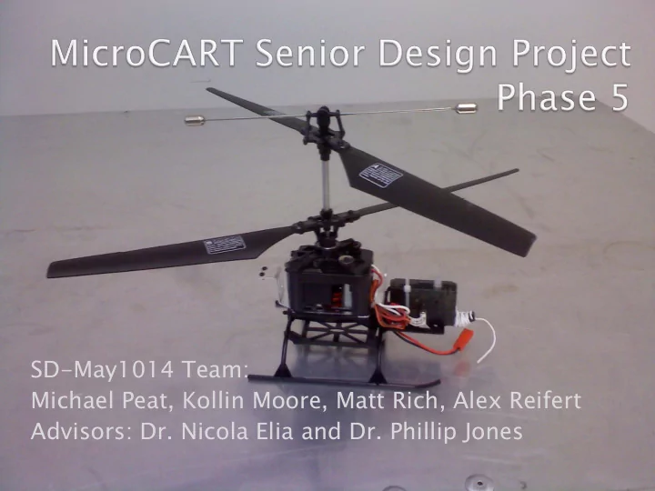
SD-May1014 Team: Michael Peat, Kollin Moore, Matt Rich, Alex Reifert Advisors: Dr. Nicola Elia and Dr. Phillip Jones
SD-May1014 Team: Michael Peat, Kollin Moore, Matt Rich, Alex Reifert - - PowerPoint PPT Presentation
SD-May1014 Team: Michael Peat, Kollin Moore, Matt Rich, Alex Reifert Advisors: Dr. Nicola Elia and Dr. Phillip Jones History MicroCART has been an active project since 1998. The project has been plagued by a: Lack of testing
SD-May1014 Team: Michael Peat, Kollin Moore, Matt Rich, Alex Reifert Advisors: Dr. Nicola Elia and Dr. Phillip Jones
History
Lack of testing availability (weather, pilot, safety issues, etc…) Lack of cooperation between successive teams and passing
Lack of consistent advising causing the lack of a systematic approach to designing a very complex end product
Rationale for project restructuring
Embry Riddle College of Engineering Carnegie Mellon University
South Dakota School of Mines and Technology (SERV Robot)
Massachusetts Institute
Technische Universitaet Berlin Georgia Tech 2009 Aerial Robotics Team
Operating Environment:
End Use and Users:
continued research and development into the area of autonomous flight systems.
engineering students and/or professors.
The system will only be operated in the
Basic flight mechanics will be achieved by
There will be a ground station. Platform will have a limited payload
There will not be obstacles in the flight
The system shall be able to take off
The system shall be able to hover
The system shall be able to land
The system shall have a minimum battery
The system shall be no larger than
The base platform shall be capable of
The base platform shall be powered solely
The system shall be capable of wirelessly
Helicopter Flight Mechanics
Radio Controller
Onboard Sensors:
Ground Station
Sensor System Power System Communication System Software System Mechanical System
Sensor System Power System Communication System Software System Mechanical System
Minimal Option: Wii-mote sensors
Single (per wii-mote)1024x768 Infrared Camera 4 Blob position tracking at 100Hz or more
3 axis Accelerometer (ADXL330) 0.04g maximum acceleration resolution on all three linear axes Free fall frame of reference Normalized output readings (g=1)
Bluetooth Transmitter Onboard Microcontroller Infrared Camera Infrared Light Emitters 3 - Axis Accelerometer
Optimal Option
OptiTrac™ optical motion capture system Six infrared cameras (lowest cost, larger numbers increase accuracy) Millimeter accuracy and resolution for the 3D location of markers depending on capture volume size and camera configuration. Currently Unavailable to us.
Highly accurate six degree of freedom accelerometer Still in production Likely ready for use mid next semester
well as several different IR camera systems
Infrared Light Emitter Infrared Cameras Direct Wired Into Ground Station 6-axis Inertial Measurement Unit Onboard FPGA's and Microcontroller Zigbee Wireless Transmitter
Accurate XYZ spatial coordinates over time Accurate Pitch Roll Yaw coordinates over time
Fast response feedback on the dynamic movements of our platform More quickly than we would be able to achieve by position sensing alone Velocity and spatial coordinates for short intervals (option 2)
Sensor System Power System Communication System Software System Mechanical System
Onboard UAV Power
7.4V, 1000 mAh 2-cell Li-Po battery pack
Originally attempted to design simple voltage divider but ran into some critical flaws:
Too much power wasted Changing load impedance
Decided to implement a step-down DC-DC (buck) converter
0-40V, 0-10A DC power supply (Model 6267B by Hewlett-Packard)
Ground Station Power
Wall plug-in for the PC/monitor
8 AA batteries or optional AC/DC wall plug-in
Sensor System Power System Communication System Software System Mechanical System
Sensor to Ground Station Communication
Broadcom 2042 HID Bluetooth
OptiTrack optical motion tracking Custom IMU
Ground Station to UAV Communications
Computer will send signals to a DAC which will send 4 separate voltages to the controller Use original 72.8 MHz FM transmitter to communicate with Base Platform Controller
Information from On- Board Sensors Computer Processor DAC to RC Controller UAV Control System
Sensor System Power System Communication System Software System Mechanical System
Data Aquisition
Input Data Transform and Filtering
both propellers.
propellers.
Controller
Speed for both propellers
Pitch for both propellers
Output Data Transform
Data Transmission
sending to the DAC described in the communications plan.
Sensor System Power System Communication System Software System Mechanical System
Sensor Mounting to Base Platform
Cradle system suspended below the battery cage Designed to produce no mid-flight instability
Will vary depending on sensor system physical dimensions and weight distribution
Testing Platforms
4 screw locations for cradle mounting
Platform
platform
Minimal Sensor System Mass (Wiimote)
interface buttons
Digital Scale
A detailed report and procedure are available on our website.
Inputs:
1) Time 2) x,y,z accelerations 3) 1st IR dot found (1 or 0) 4) 1st IR coordinates (‘x’, ‘y’) 5) 1st IR dot size (0 to 5) 6) 2nd IR dot found 7) 2nd IR coordinates 8) 2nd IR dot size
4data sets
when we can get WiiYourself source to compile
Outputs:
1) Subplots of each acceleration for each data set 2) Superimposed accelerations of all data sets 3) Subplots of pitch and roll calculated from accels for each data set 4) Superimposed pitch and roll for all data sets 5) Subplots of each set of IR points coordinates 6) Superimposed IR coordinates for all data sets 7) Superimposed xyz accelerations and pitch/roll for first data set 8) Plots of the ‘x’ and ‘y’ coordinates
9) Optional: Vectors including the minimum step sizes for each acceleration as well as angle
0.04g maximum resolution on linear axes ~2 degrees maximum resolution for pitch and roll, both by experiment and analysis Consistent outputs, though prone to some impulsive noise
1 pixel resolution at distances up to 6 ft. Optimal range of operation greater than 4 ft. from IR Very consistent static outputs Highly noisy dynamic outputs (due to high sensitivity to vibration) Optimal filtering to be determined
script available through our website
0.2 0.4 0.6 0.8 1 1.2 1.4 1.6 1.8 2 x 10
4
10 20 30 40 50 60 70 80 90 pitches
θ (degrees)
Time (ms) 2000 4000 6000 8000 10000 12000 14000 16000 50 100 pitch 1
θ (degrees)
Time (ms) 2000 4000 6000 8000 10000 12000 14000 16000 18000 50 100 pitch 2
θ (degrees)
Time (ms) 0.2 0.4 0.6 0.8 1 1.2 1.4 1.6 1.8 2 x 10
4
50 100 pitch 3
θ (degrees)
Time (ms)
470 480 490 500 510 520 530 540 550 560 377 378 379 470 480 490 500 510 520 530 540 550 560 377 378 379 460 470 480 490 500 510 520 530 540 550 560 350 400 450 460 470 480 490 500 510 520 530 540 550 560 423 424 425 469 469.1 469.2 469.3 469.4 469.5 469.6 469.7 469.8 469.9 470 350 400 450 551 552 553 5000 10000 15000 dot A x coordinate VS time x coordinate Time (ms) 5000 10000 15000 376 376.5 377 377.5 378 dot A y coordinate VS time x coordinate Time (ms) 469 470 471 5000 10000 15000 dot B x coordinate VS time x coordinate Time (ms) 5000 10000 15000 378 378.5 379 dot B y coordinate VS time x coordinate Time (ms)
8/25/2009 10/14/2009 12/3/2009 1/22/2010 3/13/2010 5/2/2010 Problem Statement Tech and Implementation Spec End Product Design Prototype Implementation End Product Testing End Product Documentation End Product Demonstration Project Reporting
Estimated Original Project Costs Section Item Cost Equipment: Base Platform Donated Replacement Parts $ 50.00 Upgraded Batteries $ 20.00 Microprocessor Board Donated IMU Donated IPS Donated Other Sensors $ 40.00 Tools and Hardware $ 40.00 Reporting: Project Poster $ 40.00 Bound Project/Design Plans $ 25.00 Labor ($20/hr): (hours) Michael Peat 350 $ 7,000.00 Kollin Moore 332 $ 6,640.00 Matt Rich 322 $ 6,440.00 Alex Reifert 320 $ 6,400.00 Subtotal (without labor): $ 215.00 Total: $ 26,695.00