
SLIDE 1
Michael Peat, Kollin Moore, Matt Rich, Alex Reifert Advisors: Dr. - - PowerPoint PPT Presentation
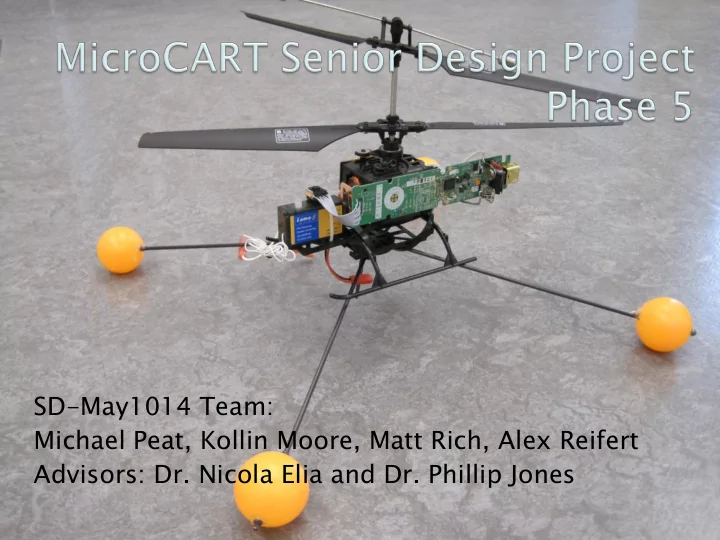
SD-May1014 Team: Michael Peat, Kollin Moore, Matt Rich, Alex Reifert Advisors: Dr. Nicola Elia and Dr. Phillip Jones Problem: To create a small electrically powered autonomous flying vehicle capable of takeoff and landing from
Solution:
The operating environment for our system will be climate controlled
Environment will be constrained by the camera limitations of the
The base platform we are using were to malfunction and become
When we are trying to write software for our control system we do
The project is too large for the time constraints we were given. Lack of funds to purchase necessary parts. Due to the complexity of the electronics and other systems that are
Since we will be using different parts from different manufacturers,
Transmitter
7.4VDC to 3.3VDC
power to sensor system
Flight testing was performed to determine how our control
Many adjustments were made in order to ensure the
15% 20% 25% 25% 15% Research Design Testing Documentation Implementation
Cost Estimate for MicroCART-Phase 5 Cost Equipment Base Platform Donated Additional Platforms $ 180.00 Replacement Parts $ 10.00 Upgraded Batteries $ 20.00 Sensors Donated Tools and hardware $ 10.00 Reporting Project Poster $ 10.00 Bound Project/Design Plans $ 15.00 Labor 1324 hours at $20 per hour $ 26,480.00 Subtotal (without labor): $ 245.00 Total: $ 26,725.00