
SLIDE 1
1
- 03 Logic networks
03.05 Digital systems
- RTL representation
- Data path and Control unit
- Project styles
- Examples
- Data transfers among registers
- BUS and Address
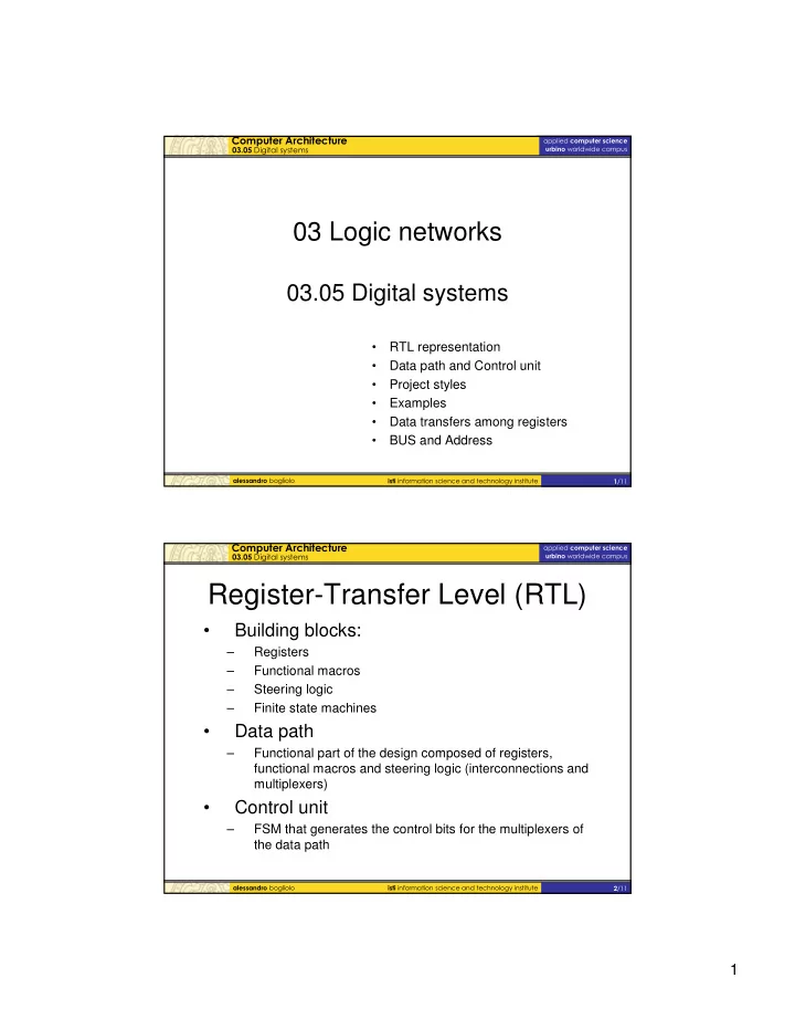
- Register-Transfer Level (RTL)
- Building blocks:
– Registers – Functional macros – Steering logic – Finite state machines
- Data path
– Functional part of the design composed of registers, functional macros and steering logic (interconnections and multiplexers)
- Control unit
– FSM that generates the control bits for the multiplexers of the data path