What Is Multicast? Key: Unicast transfer Broadcast transfer - - PDF document

what is multicast
SMART_READER_LITE
LIVE PREVIEW

What Is Multicast? Key: Unicast transfer Broadcast transfer - - PDF document

What Is Multicast? Key: Unicast transfer Broadcast transfer Unicast Multicast transfer One-to-one Destination unique Application-Level Multicast receiver host address Broadcast Routing One-to-all Destination


slide-1
SLIDE 1

1

Application-Level Multicast Routing

Michael Siegenthaler CS 614 – Cornell University November 2, 2006

A few slides are borrowed from Swati Agarwal, CS 614, Fall 2005.
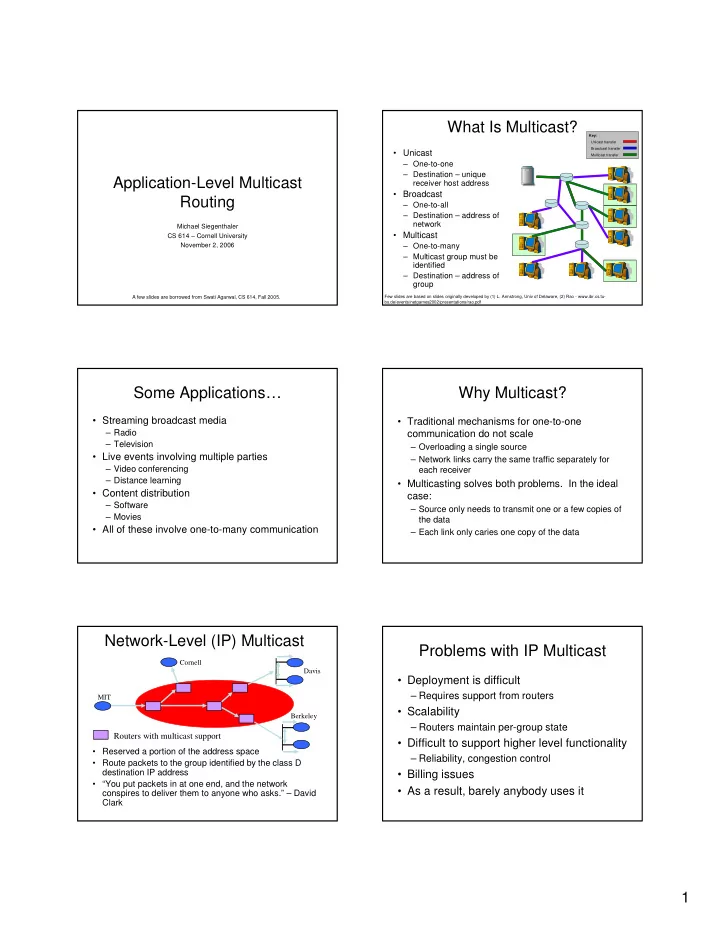
What Is Multicast?

  • Unicast

– One-to-one – Destination – unique receiver host address

  • Broadcast

– One-to-all – Destination – address of network

  • Multicast

– One-to-many – Multicast group must be identified – Destination – address of group

Key: Unicast transfer Broadcast transfer Multicast transfer

Few slides are based on slides originally developed by (1) L. Armstrong, Univ of Delaware, (2) Rao - www.ibr.cs.tu- bs.de/events/netgames2002/presentations/rao.pdf

Some Applications…

  • Streaming broadcast media

– Radio – Television

  • Live events involving multiple parties

– Video conferencing – Distance learning

  • Content distribution

– Software – Movies

  • All of these involve one-to-many communication

Why Multicast?

  • Traditional mechanisms for one-to-one

communication do not scale

– Overloading a single source – Network links carry the same traffic separately for each receiver

  • Multicasting solves both problems. In the ideal

case:

– Source only needs to transmit one or a few copies of the data – Each link only caries one copy of the data

Network-Level (IP) Multicast

Berkeley Cornell Davis MIT

Routers with multicast support

  • Reserved a portion of the address space
  • Route packets to the group identified by the class D

destination IP address

  • “You put packets in at one end, and the network

conspires to deliver them to anyone who asks.” – David Clark

Problems with IP Multicast

  • Deployment is difficult

– Requires support from routers

  • Scalability

– Routers maintain per-group state

  • Difficult to support higher level functionality

– Reliability, congestion control

  • Billing issues
  • As a result, barely anybody uses it
slide-2
SLIDE 2

2

Application layer multicast

Davis

MIT Dav1 Dav2 Berk2

Overlay Tree

Cornell Berk1

Berkeley Cornell Dav1 Dav2 Berk1 Berk2 MIT

Benefits

  • Scalability

– Routers do not maintain per group state

  • Easy to deploy

– No change to network infrastructure – Just another application

  • Simplifies support for higher level

functionality

– Can utilize existing solutions for unicast congestion control

Application-Level Multicast

  • Two basic architectures are possible

– Proxy-based

  • Dedicated server nodes exchange content among

themselves

  • End clients download from one of the servers and

do not share their data

– Peer to peer

  • All participating nodes share the load
  • “End clients” also act as servers and relay data to
  • ther nodes

A few concerns…

  • Performance penalty

– Redundant traffic on physical links

  • stress = number of times a semantically identical packet traverses a

given link

– Increase in latency

  • stretch = ratio of latency in an overlay network compared to a

baseline such as unicast or IP multicast

  • Constructing efficient overlays

– Application needs differ

  • Adapting to changes

– Network dynamics – Group membership – members can join and leave – Both of these contribute to churn

Overcast

  • Single source multicast
  • Proxy-based architecture

– Assumes nodes are well-provisioned

  • Reliable delivery

– Software or video distribution – Buffered streaming media

  • “Live” could mean delayed by seconds or minutes
  • Long term storage at each node
  • Easily deployable, seeks to minimize human

intervention

  • Works in the presence of NATs and firewalls

Components

  • Root : central source (may be replicated)
  • Node : internal overcast nodes with

permanent storage

– Organized into distribution tree

  • Client : final consumers (HTTP clients)

R Root Node Client

slide-3
SLIDE 3

3

Bandwidth Efficient Overlay Trees

10 Mb/s 1 M b / s 100 Mb/s

R

1 2

R

1 2

R

1 2

R

1 2

“…three ways of organizing the root and the nodes into a distribution tree.”

Self-Organizing Algorithm

  • A new server initially joins at the root
  • Iteratively moves farther down the tree

– Relocate under a sibling if doing so does not sacrifice bandwidth back to the root – This results in a deep tree with high bandwidth to every node

  • A node periodically reevaluates its position

– May relocate under a sibling – May become a sibling of its parent

  • Fault tolerant

– If parent fails, relocate under grandparent

Self-Organizing Algorithm

R

1 10 2 20

R

1 2 Overcast network tree Round 1 15

R

2 1 Overcast network tree Round 2

Connecting Clients

  • Client contacts the root via an HTTP

request

– Allows unmodified clients to connect – URLs provide flexible addressing

  • Hostname identifies the root
  • Pathname identifies the multicast group
  • Root redirects the client to a node which is

geographically close to the client

– Root must be aware of all nodes

Client joins

R1

1 2 3 4 5 6

R2 R3

Key: Content query (multicast join) Query redirect Content delivery

State Tracking – the Up/Down protocol

  • Each node maintains

state about all nodes in its subtree

– Reports the “births” and “deaths” among its children – Information is aggregated

  • n its way up the tree
  • Each child periodically

checks in with its parent

– Support NATs/firewalls

1 1.1 1.2 1.3 1.2.1 1.2.3 1.2.2 1.2.2.1

Birth certificates for 1.2.2, 1.2.2.1 No change

  • bserved.

Propagation halted.

slide-4
SLIDE 4

4

Is The Root Node A Single Point Of Failure?

  • Root is responsible for handling all join requests

from clients

– Note: root does not deliver content

  • Root’s Up/Down protocol functionality can not be

easily distributed

– Root maintains state for all Overcast nodes

  • Solution: configure a set of nodes linearly from

root before splitting into multiple branches

– Each node in the linear chain has sufficient information to assume root responsibilities – Natural side effect of Up/Down protocol

Evaluation Evaluation

Lease period = how long a parent will wait to hear from a child before reporting its death

Evaluation Overcast Conclusion

  • Designed for software, video distribution

– Bit-for-bit integrity, not time critical

  • Could fullfill a similar role as content

distributions systems such as Akamai

  • Also works for “live” streams, if sufficient

buffering delay is used

Enabling Conferencing Applications

  • n the Internet using an Overlay

Multicast Architecture

  • Latency and bandwidth are important

– Real-time interaction between users

  • Evaluates how to optimize for dual metrics
  • Small-scale (10s of nodes) peer to peer

architecture

– Single source at any given time

  • Gracefully degradable

– Better to give up on lost packets than to retransmit and have them arrive too late to be useful

slide-5
SLIDE 5

5

Self-Improving Algorithm

  • Two-step tree building process (Narada)

– Construct a mesh, a rich connected graph – Choose links from the mesh using well-known routing algorithms

  • Routing chooses shortest widest path

– Picks highest bandwidth, and opts for lowest latency when there are multiple choices – Exponential smoothing and discrete bandwidth levels are used to deal with instability due to dynamic metrics

Evaluation

  • Schemes for constructing overlays

– Sequential Unicast

  • Hypothetical construct for comparisons purposes

– Random

  • Baseline to compare against

– Latency-Only – Bandwidth-Only – Bandwidth-Latency

Evaluation Comparison of schemes

  • Primary Set – 1.2 Mbps
  • Primary Set – 2.4 Mbps
  • Extended Set – 2.4 Mbps
  • Primary Set contains well connected nodes

– North American university sites

  • Extended Set – more heterogeneous

environment

– Some ADSL links, hosts in Europe and Asia

Bandwidth – primary set, 1.2 Mbps Bandwidth – extended set, 2.4 Mbps

slide-6
SLIDE 6

6

RTT – extended set, 2.4 Mbps Conclusion

  • It is possible to build overlays that optimize

for both bandwidth and latency

  • Unclear whether these results scale to

larger group sizes

More Recent Work

  • SplitStream

– Uses multiple overlapping trees

  • Various DHT-based approaches
  • BitTorrent

– Unstructured, random graphs

Discussion Questions

  • Is a structured overlay the right approach,
  • r is something more random better?

– How much do we really care about stress or stretch?

  • Both papers mainly use heuristics

– Could a more mathematically based approach do better?