
1
4/16/2004 CSE378 Single cycle implementation. 1
Levels in Processor Design
- Circuit design
– Keywords: transistors, wires etc.Results in gates, flip-flops etc.
- Logical design
– Putting gates (AND, NAND, …) and flip-flops together to build basic blocks such as registers, ALU’s etc (cf. CSE 370)
- Register transfer
– Describes execution of instructions by showing data flow between the basic blocks
- Processor description (the ISA)
- System description
– Includes memory hierarchy, I/O, multiprocessing etc
4/16/2004 CSE378 Single cycle implementation. 2
Register transfer level
- Two types of components (cf. CSE 370)
– Combinational : the output is a function of the input (e.g., adder) – Sequential: state is remembered (e.g., register)
4/16/2004 CSE378 Single cycle implementation. 3
Synchronous design
- Use of a periodic clock
– edge-triggered clocking determines when signals can be read and when the output of circuits is stable – Values in storage elements can be updated only at clock edges – Clock tells when events can occur, e.g., when signals sent by control unit are obeyed in the ALU
- Stor. Elem 1
- Stor. Elem 2
Comb.logic Clock cycle
Note: the same storage element can be read/written in the same cycle
4/16/2004 CSE378 Single cycle implementation. 4
- Stor. Elem 1
- Stor. Elem 2
Comb.logic
Write signal Write signal Logic may need several cycles to propagate values True in designs today with very high clock frequency
4/16/2004 CSE378 Single cycle implementation. 5
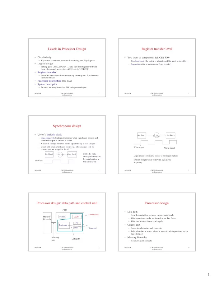
Processor design: data path and control unit
Memory hierarchy control ALU Registers PC state Memory bus CPU Data path
Combinational Sequential 4/16/2004 CSE378 Single cycle implementation. 6
Processor design
- Data path
– How does data flow between various basic blocks – What operations can be performed when data flows – What can be done in one clock cycle
- Control unit
– Sends signals to data path elements – Tells what data to move, where to move it, what operations are to be performed
- Memory hierarchy
– Holds program and data