
SLIDE 1
July 21, 2004 SKA2004, Pentiction B.C. p1 of 23
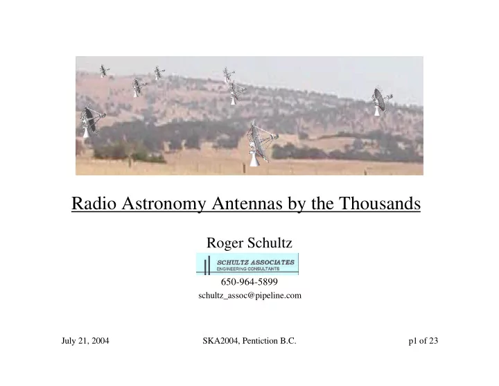
Radio Astronomy Antennas by the Thousands
Roger Schultz
650-964-5899
schultz_assoc@pipeline.com
Radio Astronomy Antennas by the Thousands Roger Schultz - - PowerPoint PPT Presentation
Radio Astronomy Antennas by the Thousands Roger Schultz 650-964-5899 schultz_assoc@pipeline.com July 21, 2004 SKA2004, Pentiction B.C. p1 of 23 Cost Effective Radio Telescope Development Existing cost expectations, established by ATA
July 21, 2004 SKA2004, Pentiction B.C. p1 of 23
schultz_assoc@pipeline.com
July 21, 2004 SKA2004, Pentiction B.C. p2 of 23
July 21, 2004 SKA2004, Pentiction B.C. p3 of 23
July 21, 2004 SKA2004, Pentiction B.C. p4 of 23
July 21, 2004 SKA2004, Pentiction B.C. p5 of 23
July 21, 2004 SKA2004, Pentiction B.C. p6 of 23
July 21, 2004 SKA2004, Pentiction B.C. p7 of 23
July 21, 2004 SKA2004, Pentiction B.C. p8 of 23
Upper: chordal linkages guide drilling of target mounting holes. Right: Schultz instructs height adjustment to setting angle. 30 meter domsat antenna, circa 1970’s
July 21, 2004 SKA2004, Pentiction B.C. p9 of 23
F ig u r e 1 reflective sheet is h e ld d
n
July 21, 2004 SKA2004, Pentiction B.C. p10 of 23
July 21, 2004 SKA2004, Pentiction B.C. p11 of 23
July 21, 2004 SKA2004, Pentiction B.C. p12 of 23
July 21, 2004 SKA2004, Pentiction B.C. p13 of 23
July 21, 2004 SKA2004, Pentiction B.C. p14 of 23
0.002 0.004 0.006 0.008 0.01 0.012 0.014 0.016 0.018 0.02 1 2 3 4 5 6 Radial Distance (m) Springback (m)
July 21, 2004 SKA2004, Pentiction B.C. p15 of 23
July 21, 2004 SKA2004, Pentiction B.C. p16 of 23
eliminates most diagonals
July 21, 2004 SKA2004, Pentiction B.C. p17 of 23
July 21, 2004 SKA2004, Pentiction B.C. p18 of 23
July 21, 2004 SKA2004, Pentiction B.C. p19 of 23
July 21, 2004 SKA2004, Pentiction B.C. p20 of 23
arm
July 21, 2004 SKA2004, Pentiction B.C. p21 of 23
calculations compliments of Bill Imbrialli, JPL)
July 21, 2004 SKA2004, Pentiction B.C. p22 of 23
July 21, 2004 SKA2004, Pentiction B.C. p23 of 23