Protection components TeSys T Motor Management System Presentation - - PDF document

protection components
SMART_READER_LITE
LIVE PREVIEW

Protection components TeSys T Motor Management System Presentation - - PDF document

Presentation Protection components TeSys T Motor Management System Presentation 1 2 TeSys T is a motor management system that provides protection, metering and PF526378-63-M.eps monitoring functions for single-phase and 3-phase, constant


slide-1
SLIDE 1

6/70

Presentation

TeSys T is a motor management system that provides protection, metering and monitoring functions for single-phase and 3-phase, constant speed, a.c. motors up to 810 A. Suitable for the harshest applications, this product range offers: b high-performance multifunction protection, independent of the automation system b a local HMI control unit for reading, displaying and modifying the parameters monitored, diagnostics, etc. b confjguration of the application using SoMove software b connection to the automation system via a communication network (selection according to various protocols).

Application

The TeSys T motor management system is used for motor control and protection in harsh industrial applications, in which downtime must be avoided because it is very costly: Oil & Gas, chemical industry, water treatment, metal, minerals and mining, pharmaceutical industry, microelectronics, tunnels, airports etc. With TeSys T, untimely stoppages of a process or manufacturing, associated with a motor, are anticipated via predictive analysis of fault situations. Fault tripping is therefore reduced to a minimum. Its use in motor control panels makes it possible to: b increase the operational availability of installations b improve fmexibility from project design through to implementation b increase productivity by making available all information needed to run the system. The TeSys motor management system integrates perfectly with Schneider Electric low voltage equipment, such as Okken, Blokset and Prisma. 1 Magnetic circuit-breaker 2 Contactor 3 Controller with extension module 4 Operator control unit

Presentation

Protection components

TeSys T Motor Management System

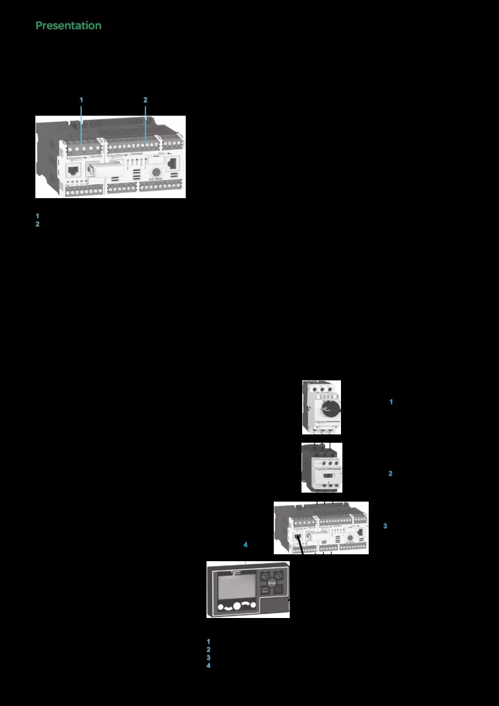
1 LTM EV40BD extension module 2 LTM R08MBD controller 1 2

PF526378-63-M.eps

3

M 3

1 2 4

DF526392.eps

24656-EN Version : 6.1 14/01/2013

slide-2
SLIDE 2

6/71

Presentation

Composition of the motor management system

The system comprises: b an LTM R motor management controller v with integral current transformer up to 100 A v above 100 A, by external current transformer up to 810 A b an LTM E extension module b an LTM CU operator control unit b confjguration software incorporated in the SoMove software application b accessories for system set-up. Communication The LTM R controller is equipped with a communication interface to allow remote monitoring and control of the motor. All motor information is then available at automation system level. The following networks are available: b Modbus, CANopen, DeviceNet, ProfjBus DP and Ethernet TCP/IP.

TeSys T system functions

Protection functions: b against thermal overload b against phase imbalance and phase failure b thermal motor protection via PTC probes b against phase reversal b against earth faults b against long starting times and motor stalling b against automatic load shedding and restarting b against load fmuctuations (I, U, P) b against variations of Cos ϕ (power factor). Metering functions b Measurements (rms values): v current on the 3 phases v voltage on the 3 phases (shedding) v motor temperature v earth fault. b Values calculated: v average current v frequency v Cos ϕ (power factor), power, power consumption... Motor control functions A motor managed by TeSys T can be controlled: b locally, using the logic inputs present on the product, or via the HMI terminal b remotely, via the network (connection by terminal block or connector except for DeviceNet: terminal block only). Motor control modes 5 predefjned motor control modes are incorporated in the controller: b overload mode: monitoring of motors whose control is not managed by the controller, b independent mode: starting of non-reversing motors, b reverser mode: starting of reversing motors, b 2-step mode: 2-step starting of motors (star-delta, by autotransformer and by resistor), b 2-speed mode: 2-speed starting of motors (Dahlander, pole changer). A 6th “Custom” mode is available to allow the user to create a specifjc motor control mode that is not predefjned in the controller. Statistical and diagnostic functions b Fault statistics: counters per type of protection and history of the last 5 faults. b Motor statistics: saving of motor statistics values. b Diagnosis of faults affecting correct operation of the product.

Presentation

Protection components

TeSys T Motor Management System

LTM R08MBD

PF526379-47-M.eps

LTM EV40BD

PF526380-30-M.eps

LTM CU

PF568605-44-M.eps

24656-EN Version : 6.1 14/01/2013

6

slide-3
SLIDE 3

6/72

Description

The LTM R controller

The controller is the central component in the motor management system. It manages the basic functions such as: b measurement of 3-phase current via integral current transformers from 0.4 to 100 A (up to 810 A by external current transformers) b measurement of earth current by external earth fault toroid b measurement of motor temperature by PTC probe b inputs and outputs for the various motor control modes, fault management and associated functions.

Characteristics

As standard, the controller manages the following predefjned control mode functions: b overload mode b independent mode b reverser mode b 2-speed mode b 2-step mode b "Custom" mode. Supply 2 types of controller power supply are available: b c 24 V b a 100…240 V. To AC (FM) versions only and for certain conditions of use, an external fjlter (LTM9F) must be used upstream of TeSys T. Conditions of use:

LTMR Power Supply Filter use

U > 240 V AC Always use the LTM9F fjlter 150 V AC < U < 240 V AC Recommended to use the LTM9F fjlter in highly disturbed environments such as : b Variable Speed Drive in installation close to the TeSys T and/or without upstream self. b Or long line wiring for I/O (over 400 m). b Or dirty / dusty corrosive environments that might affect installation grounding quality. b Or no surge suppressor on contactor coils. b Or unstable voltage of auxiliary supply. U < 150 V AC Do not use any fjlter.

This fjlter must only supply the LTM R relay and its inputs. The output supply must be connected upstream of this fjlter. Current ranges 3 current ranges allow measurement of motor current from 0.4 to 100 A: b 0.4…8 A b 1.35…27 A b 5…100 A. For use with external current transformers, choose the 0.4…8 A range (1 or 5 A current transformer secondary). Inputs b 6 discrete logic inputs. Outputs b 3 relay logic outputs (1N/O). b 1 relay output for fault signalling (1N/O + 1N/C). Measurements b Connections for a temperature probe. b Connections for an earth fault toroid.

LTM E extension module

The extension module adds the following functionalities to the TeSys T controller: b voltage measurement on the 3 phases. This enables it to calculate numerous engine monitoring parameters (power, frequency, Cos ϕ …) b 4 additional inputs.

Characteristics

Inputs b 4 discrete logic inputs (independent). Power supplies b 2 types of power supply for the inputs: c 24 V and a 100…240 V. A c 24 V controller can be assembled with an a 100…240 V extension module and vice versa. Voltage measurement between phases up to 690 V nominal.

Protection components

TeSys T Motor Management System

LTM Rpp

PF526381-44-M.eps

24656-EN Version : 6.1 14/01/2013

slide-4
SLIDE 4

6/73

Human/Machine Interfaces (HMI)

Depending on the application, 2 types of HMI can be used with the LTM R controller. b The LTM CU operator control unit: v entirely dedicated to the TeSys T range v only for control/monitoring of an LTM R controller. b A Magelis XBT N410 terminal for control/monitoring of 1 to 8 LTM R controllers.

LTM CU operator control unit

Dedicated exclusively to TeSys T controllers, control unit LTM CU makes it possible to: b confjgure the parameters of the LTM R controller b display information on controller confjguration and operation b monitor the alarms and faults generated by the controller b local control of the motor via the local control interface (keys can be customised). Three different languages can be loaded into the LTM CU controller at the same time. By default, these 3 languages are: b LTM CU: English, French and Spanish b LTM CU01: English, Chinese and Indonesian. Note: English is the only compulsory language. A language download utility (LangTool), together with all the other languages, are available on the website “www.schneider-electric.com”. This tool allows the languages present in the LTM CU control unit to be adapted. The LTM CU HMI control unit has an RJ45 port, protected by a fmexible cover to provide a good level of protection (IP54). This port on the front panel allows connection to a PC, via a connecting cable, in order to use SoMove software. In this case, the control unit acts as a transmitter and all information can then be viewed in SoMove. The LTMCU HMI can be used as a portable version by using the separate kit

  • LTM9KCU. This kit consists of two snap-on plastic shells (tool-free mounting) fjtted

with a simple fjxing system that uses magnets for mounting on all types of metal surfaces.

The Magelis XBT N410 HMI terminal

Two applications have been predefjned for TeSys T. Depending on the application loaded, the HMI terminal makes it possible to: b confjgure and monitor a motor starter (LTM_1T1_V1.dop) b monitor and modify certain parameters on up to 8 motor starters (LTM_1T8_X_V1.dop) (1). XBT L1000 programming software is needed for loading applications into the HMI terminal. These applications are available on the website “www.schneider-electric.com”.

(1) Replace the X with an E for the English version, or an F for the French version.

Description

Protection components

TeSys T Motor Management System

LTM CU

568606-M.eps

24656-EN Version : 6.1 14/01/2013

6

slide-5
SLIDE 5

6/74

Description

LTM R controllers

Modbus DeviceNet 2 3 4 6 7 10 8 1 9 5

PF526381-44-M.eps

2 3 4 7 10 8 1 9 5

PF526382-44-M.eps

Controllers feature the following on their front panel: 1 Controller power supply. 2 Input connections. 3 Fault outputs (N/O+N/C). 4 Port for connection to the HMI terminal, a PC or an extension module (RJ45). 5 Controller status LEDs. 6 Network port for connection to the network by connector (except DeviceNet) (1). 7 Test/Reset button. 8 Connection to the network by terminal block (except Ethernet TCP/IP). 9 Connection for an earth fault toroid and temperature probes. 10 Outputs for motor control mode function. Profjbus DP CANopen 2 3 4 6 7 10 8 1 9 5

PF526383-44-M.eps

2 3 4 6 7 10 8 1 9 5

PF526384-44-M.eps

Ethernet TCP/IP 2 3 4 6 10 1 9 5 7 6

PF526385-45-M.eps

(1) Connection using power extension (daisy- chaining) is possible for Ethernet TCP/IP.

LTM EV40pp extension modules LTM CU operator control unit

1 2 3 5 4

PF526386-22-M.eps

1 2 3 4

PF568607-34-M.eps

Extension modules have the following on their front face: 1 Inputs for voltage measurement. 2 Port for connection to the HMI terminal or to the PC. 3 Port for connection to the controller. 4 Extension module status LEDs. 5 Connection of additional inputs. The control unit has the following on its front face: 1 Screen LCD display. 2 Local control interface including control keys and LEDs. 3 RJ45 port on front panel for connection to a PC (protected by a cover). 4 Contextual navigation keys.

Protection components

TeSys T Motor Management System

24656-EN Version : 6.1 14/01/2013

slide-6
SLIDE 6

6/75

Thermal and current protection functions

Functions Setting range Controller LTM R Controller and extension module (LTM R + LTM E) Alarm threshold Fault threshold Description Thermal overload: thermal protection of motor by monitoring current consumption Class: 5, 10, 15, 20, 25, 30. Inverse ther/defjnite time Motor temperature: thermal monitoring of the motor using temperature probes (winding, paper...). Up to 3 sensors in series. PTC binary PTC/NTC analogue: 20 …6500 Ohm Phase imbalance: monitors the symmetry of currents. To be used for imbalance < 80% of the average current (1). 10…70% I average 0.2…20 s Phase failure: monitors the symmetry of currents. To be used for imbalance < 80% of the average current (1). 0.1…30 s Phase reversal: signals when the phase sequence is different from the defjned sequence (motor running). A-B-C A-C-B Long starting time: monitors the motor starting time 100…800 % of FLC (2) 1…200 s Locked rotor: locking detected by a sudden increase in current after the start phase 100…800 % of FLC (2) 1…30 s Min/max current load limit variations: monitors motor load through variations of current around preset thresholds. min.: 30…100 % of FLC (2) 1…200 s max.: 20…800 % of FLC (2) 1…250 s Earth fault: signals internal insulation faults, by vectorial summing

  • f external currents, via earth fault toroid.

internal: 20…500 % min FLC (2) 0.05…25 s external: 0.02…10 A 0.05…25 s Frequent starting: Protects the motor against overheating due to frequent starting. 0…999.9 s

Voltage and power protection functions

Phase imbalance: monitors the symmetry of voltage between phases. To be used for imbalance < 40 % of the average voltage (3). 3…15 % 0.2…20 s Phase failure: monitors the symmetry of voltage between phases. To be used for imbalance > 40 % of the average voltage (3). 0.1…30 s Phase reversal: signals when the phase sequence is different from the defjned sequence (motor stopped). A-B-C A-C-B Voltage variations. Min/max voltage limits: monitors voltage variations around preset thresholds. min.: 70…99 % 0.2…25 s max.: 101…115 % 0.2…25 s Load shedding:

  • pens outputs O.1 and O.2 if voltage drops below a preset

threshold. 68…115 % 1…9999 s Power variations. Min/max power limits: monitors power variations around preset thresholds. 20…800 % 0…100 s Variations of Cos ϕ. Min/max limits of Cos ϕ : monitors variations of Cos ϕ around preset thresholds. 0…10…25 s Function performed. (1) Average current value measured on the 3 phases. (2) FLC: Full Load Current (setting current). (3) Average voltage value measured on the 3 phases.

Functions

Protection components

TeSys T Motor Management System

24656-EN Version : 6.1 14/01/2013

6

slide-7
SLIDE 7

6/76

Functions

Motor control functions

Functions Description With controller LTM R With controller LTM R and extension module LTM E Control modes Local, via terminal block X X Local, via HMI terminal (1) X X Remote, via network X X Operating modes Overload X X Independent X X Reverser X X 2-step X X 2-speed X X "Custom" mode X X Fault management Manual reset X X Automatic reset X X Remote reset X X

Metering functions and statistics

Functions Description Measurement range With controller LTM R With controller LTM R and extension module LTM E Measurements (2) Current/Phase 0.08…1000 A X X Earth current 0.1633 x CT ratio X X Average current 0.08…1000 A X X Current imbalance between phases 0…200 % X X Thermal capacity level 0…200 % X X Motor temperature rise 0…6500 Ohm X X Frequency 0… 100 Hz X Voltage between phases a 0…830 V X Voltage imbalance between phases 0…200 % X Active power 0…6553.5 kW X Reactive power 0…6553.5 kWr X Cos ϕ (power factor) 0…100 X Active power consumption 0…400 kWh X Reactive power consumption 0…400 kWrh X Fault statistics Protection fault counters X X Protection alarm counters X X Diagnostic fault counters X X Motor control function counters X X Fault history X X Fault diagnostics Internal watchdog fault X X Controller internal temperature X X Temperature sensor connection X X Current connection X X Voltage connection X Motor control commands (start, stop, run check back and stop check back) X X Control confjguration checksum X X Loss of communication X X Motor statistics Number of motor control commands (O.1/O.2 starts) X X Operating time X X Number of starts/hour X X Last start I max. X X Duration of last start X X Thermal overload statistics Time to trip X X Time to restart X X System operating statistics Run, ON, Start, alarm, fault. X X (1) HMI: Human Machine Interface. (2) See measurement details page 6/82.

Protection components

TeSys T Motor Management System

24656-EN Version : 6.1 14/01/2013

slide-8
SLIDE 8

6/77

Service classes offered by the Ethernet TCI/IP version

Class A 20 ETH10/100 + FTP server Basic Web server None Basic communications services Ethernet TCP/IP Modbus messaging (read/write of data words) Ethernet TCP/IP communication advanced management services I/O Scanning Yes Global Data No Client FDR (1) Automatic monitoring and updating of product parameter confjguration. Automatic assignment of IP address and network parameters. SNMP network administrator (2) Yes

Ethernet: different network topologies

Star topology In a star topology, all the peripherals are linked via an intermediate peripheral (hub or switch). In industrial Ethernet applications, the use of full duplex switches (instead of hubs) as central peripherals is strongly recommended. Power extension (Daisy chain) topology Power extension (or Daisy chaining), at bus level, is another connection topology commonly used in traditional, industrial automation system networks. The cable segments link several peripherals to each other, constituting the peripheral "section"

  • f the network cable.

Ethernet Power extension (Daisy chain) Power extension is not yet a very commonly used Ethernet connection topology, but will quickly become so when a large number of peripherals are made available in the market. In an Ethernet power extension topology, the peripherals have: b 2 Ethernet ports b and an integrated switch. Schneider Electric is progressively introducing, into the industrial market, Ethernet peripherals that can be used in daisy chain type architectures. Implementation of a power extension topology No hub or switch is required for using a power extension topology. Each peripheral must have an integrated switch (two ports). A port on the peripheral is connected to a port on the neighbouring upstream and downstream peripherals. These consecutive connections constitute the power extension (daisy chain). Ethernet switches may be included in a power extension (daisy chain) topology when several scan chains are used by the monitoring peripheral. The Ethernet switch must be installed close to the monitoring peripheral, with the various scan chains coming from the switch.

(1) FDR: Faulty Device Replacement. (2) SNMP: Simple Network Management Protocol.

Functions, Topology

Protection components

TeSys T Motor Management System

TeSys T TeSys T TeSys T TeSys T

Star topology

DF525872.eps

TeSys T TeSys T TeSys T

Daisy chain topology

DF525878.eps

24656-EN Version : 6.1 14/01/2013

6

slide-9
SLIDE 9

6/78

Ethernet: different network topologies

Ring topology In a ring topology, all the peripherals or components of the network infrastructure are connected within a loop. This type of topology makes it possible to achieve different levels of redundancy of the network. Ethernet ring Ethernet rings are generally the main networks in applications where a high level of reliability is required. If a ring topology is required, the switches handling this function must be used. Redundancy Redundancy of the network infrastructure is the key to development of applications with high operational reliability. Implementing a single or double ring architecture makes it possible to provide protection against breaks in network segments. Single ring The fjrst level of redundancy can be achieved by installing a single ring. ConneXium switches can be used to establish main network ring confjgurations. The ring is created using HIPER-Ring ports. If a section of the line fails, the ring structure (including a maximum of 50 switches) converts into a line type confjguration in less than 0.5 seconds.

Topology

Protection components

TeSys T Motor Management System

TeSys T TeSys T TeSys T TeSys T

Ring topology

DF525871.eps

24656-EN Version : 6.1 14/01/2013

slide-10
SLIDE 10

6/79

Possible confjgurations and applications

LTM CU TeSys T TeSys T TeSys T SoMove LTM CU SoMove

DB414717.eps

PLC (automation platform) Network or bus

  • r

Programming

Protection components

TeSys T Motor Management System

24656-EN Version : 6.1 14/01/2013

6

slide-11
SLIDE 11

6/80

Programming

Confjguration with SoMove

The TeSys T confjgurator is incorporated in the SoMove software application, as from version 2.5. (1) It allows confjguration, commissioning and maintenance of motor starters protected by TeSys T. A library containing predefjned motor control mode functions is available in order to: b allow standardisation b avoid errors b reduce motor starter setup times. 5 predefjned motor control modes are incorporated in the controller: b overload mode: monitoring of motors whose control is not managed by the controller b independent mode: starting of non-reversing motors b reverser mode: starting of reversing motors b 2-step mode: 2-step starting of motors (star-delta, by autotransformer and by resistor) b 2-speed mode: 2-speed starting of motors (Dahlander, pole changer). By using logic functions, a "Custom" mode makes it possible to: b easily adapt these predefjned motor control mode functions to the specifjc needs

  • f your applications

b create a link with the motor starter environment or b create new functions. The functions thus defjned can be saved and used to build your function library for future applications. To create special functions, a logic editor is incorporated in the confjgurator and allows a choice of 2 programming languages: b function block b structured text.

(1) An update fjle is available, free of charge, on the website “www.schneider-electric.com”. It will enable you to take advantage of the latest functions in the TeSys T motor management system.

Protection components

TeSys T Motor Management System

Example of TeSys T confjgurator setup screen

DF568609.eps

Example of logic editor screen.

DF536196.eps

24656-EN Version : 6.1 14/01/2013

slide-12
SLIDE 12

6/81

Characteristics

Environment

Product type LTM R controllers LTM EV40pp extension modules Conforming to standards IEC/EN 60947-4-1, UL 508, CSA 22-2 n°14, IACS E10 Product certifjcations UL, CSA,BV, LROS, DNV, GL, RINA, ABS, RMRos, NOM, CCC, C-TIC’K, ATEX, GOST, KERI (1) Rated insulation voltage

  • f the outputs (Ui)

Conforming to IEC/EN 60947-1,

  • vervoltage category III,

degree of pollution 3 V 690 Conforming to UL 508, CSA C222 n° 14 V 690 Rated impulse withstand voltage (Uimp) Conforming to IEC/EN 60947-4-1 a 100…240 V supply, inputs and outputs kV 4 4 c 24 V supply, inputs and outputs kV 0.8 0.8 Communication circuits kV 0.8 – Current or voltage measurement circuit kV 6 6 Short-circuit withstand Conforming to IEC/EN 60947-4-1 kA 100 Protective treatment Conforming to IEC/EN 60068 “TH” Conforming to IEC/EN 60068-2-30 12 x 24 hour cycles Conforming to IEC/EN 60070-2-11 h 48 Ambient air temperature around the device Storage °C

  • 40…+80

Operation °C

  • 20…+60

Operating position without dating In relation to normal vertical mounting plane ±30° in relation to mounting plate, ±90°

DF568612.eps DF568613.eps

Flame resistance Conforming to UL 94 °C 960 (for parts supporting live components) Conforming to IEC/EN 60695-2-12 °C 650 (for other parts) Shock resistance (1/2 sine wave, 11 ms) Conforming to IEC/EN 60068-2-27 (2) 15 gn Vibration resistance Conforming to IEC/EN 60068-2-6 (2) 5…300 Hz 4 gn (plate mounted) 1 gn (mounted on 5 rail) Resistance to electrostatic discharge Conforming to IEC/EN 61000-4-2 kV In open air: 8 - Level 3 On contact: 6 - Level 3 Immunity to radiated electromagnetic interference Conforming to IEC 61000-4-3 V/m 10 - Level 3 Immunity to fast transient bursts Conforming to IEC 61000-4-4 kV On supply and relay outputs: 4 - Level 4 Other circuits: 2 - Level 3 Immunity to radioelectric fjelds Conforming to IEC/EN 61000-4-6 V 10 - Level 3 Immunity to dissipated shock waves Conforming to IEC/EN 61000-4-5 Common mode Serial mode Common mode Serial mode Relay outputs and supply kV 4 2 – – c 24 V inputs kV 1 1 1 1 a 100…240 V inputs kV 2 1 2 1 Voltage inputs kV – – 4 2 Communication kV 2 – 2 – Temperature sensor (IT1/IT2) kV 1 0.5 – – Altitude derating 2000 m 3000 m 3500 m 4000 m 4500 m Rated operational voltage (Ui) 1 0.93 0.87 0.8 0.7

  • Max. operating temperature

1 0.93 0.92 0.9 0.88 (1) Certain certifjcations are pending; please consult your Customer Care Centre. (2) Without modifying the contact states, in the most unfavorable direction.

Protection components

TeSys T Motor Management System

24656-EN Version : 6.1 14/01/2013

6

slide-13
SLIDE 13

6/82

Characteristics

Controller and extension module characteristics

Product type Controllers Extension modules LTM RpppBD LTM RpppFM LTM EV40BD LTM EV40FM

Control supply

Operational voltage (U) Conforming to IEC/EN 60947-1 V c 24 a 100…240 – Resistance to voltage dips Conforming to IEC/EN 61000-4-11 V 0 for 3 ms 70 % of U for 500 ms – Associated protection A gG fuse, 0.5 – Operational voltage (1) Limit values V c 20.4…26.24 a 93.5…264 – Current consumption 50/60 Hz mA c 56…127 a 8…62.8 – Connectors Pitch mm 5.08 5.08 Flexible cable without cable end 1 conductor mm2 0.2…2.5 0.2…2.5 2 identical conductors mm2 0.2…1.5 0.2…1.5 Flexible cable with cable end Without insulated ferrule 1 conductor mm2 0.25…2.5 0.25…2.5 2 identical conductors mm2 0.5…1.5 0.5…1.5 With insulated ferrule 1 conductor mm2 0.25…2.5 0.25…2.5 2 identical conductors mm2 0.2…1 0.2…1 Solid cable without cable end 1 conductor mm2 0.2…2.5 0.2…2.5 2 identical conductors mm2 0.2…1 0.2…1 Conductor size AWG 24 to AWG 14 AWG 24 to AWG 14 Tightening torque N.m 0.5…0.6 0.5…0.6 Flat screwdriver mm 3 3

Input characteristics

Nominal values Conforming to IEC/EN 61131-1 Type 1 positive logic (c: resistive, a: capacitive) Voltage V c 24 a 100…240 c 24 a 100…240 Current mA c 7 a 3.1 for 100 V a 7.5 for 240 V c 7 a 3.1 for 100 V a 7.5 for 240 V Logic inputs Logic state 1 Voltage V 15 max 79 < U < 264 15 max 79 < U < 264 Current mA 2 min…15 max 2 min at 110 V… 3 min at 220 V 2 min…15 max 2 min at 110 V… 3 min at 220 V Logic state 0 Voltage V 5 max 0 < U < 40 5 max 0 < U < 40 Current mA 15 max 15 max 15 max 15 max Response time Change to state 1 ms 15 25 15 25 Change to state 0 ms 5 25 5 25

Output characteristics

Type Volt free, single break Load a 250 V / 5 A B300 c 30 V / 5 A Permissible power in cat. AC-15 For 500 000 operating cycles VA 480 / Ie max: 2 A Permissible power in cat. DC-13 For 500 000 operating cycles W 30 / Ie max: 1.25 A Associated protection A gG fuse, 4

  • Max. frequency

Hz 2

  • Max. operating level
  • p.

cycles/h 1800 Response time Change to state 1 ms 10 max Change to state 0 ms 10 max

Measurement details

Current 1 % for the 0.4…8 A and 1.35…27 A ranges 2 % for the 5…100 A range Voltage 1% from 100 to 830 V Earth fault current Internal measurement without earth fault toroid 5…15 % for current > 0.1 A in the 0.4…8 A range current > 0.2 A in the 1.35…27 A range current > 0.3 A in the 5…100 A range External measurement with earth fault toroid < 5 % or 0.01 A Temperature measurement 2 % Power factor 10 % Active and reactive power 15 % Internal clock ± 30 min / year

Protection components

TeSys T Motor Management System

24656-EN Version : 6.1 14/01/2013

slide-14
SLIDE 14

6/83

Bus and network characteristics

Type of bus/network Modbus CANopen DeviceNet Profjbus DP Ethernet Physical interface 2-wire RS 485 ISO 11898 ISO 11898 polarised 2-wire RS 485 IEEE 802.3 Addressing 1 to 247 1 to 127 1 to 64 1 to 125 0 to 159 Transmission speeds 1.2 to 19.2 kb/s 10, 20, 50, 125, 250, 500, 800 and 1000 kb/s + Auto baud 125 to 500 kb/s 9.6 kb to 12 Mb/s 10/100 Mb/s, with automatic recognition Connections RJ45/terminal block 9-way SUB-D/ terminal block Terminal block 9-way SUB-D/ terminal block RJ45 Cables 2 shielded twisted pairs 4 twisted, shielded wires 4 twisted, shielded wires 2 shielded twisted pairs, type A 2 shielded twisted pairs

LTM CU operator control unit

Environment

Conforming to standards IEC/EN 61131-2, UL 508, CSA 22-2 n°14 Product certifjcations UL, CSA, CE, C-TIC’K, NOM, GOST Ambient air temperature around the device Storage °C

  • 40…+80

Operation °C

  • 20…+60

Relative humidity 15…95 % without condensation Protective treatment Conforming to IEC/EN 60068-2-30 12 x 24 hour cycles Degree of protection Conforming to IEC 60947-1 IP54 Shock resistance Conforming to IEC/EN 60068-2-27 15 gn / 11ms Vibration resistance Conforming to IEC/EN 60068-2-6 5…30 Hz 4 gn Flame resistance Conforming to IEC 60947-1 °C 650 Conforming to UL 94 V2

Electrical characteristics

Supply to the product Powered via the controller Maximum current mA 140 Maximum power dissipated W 1 Resistance to electromagnetic discharge Conforming to IEC/EN 61000-4-2 kV In open air: 8. Level 3 On contact: 4. Level 3 Immunity to radiated electromagnetic interference Conforming to IEC/EN 61000-4-3 V/m 10 - Level 3 Immunity to fast transient bursts Conforming to IEC/EN 61000-4-4 kV 2, shielded access. Level 3 Immunity to radioelectric fjelds Conforming to IEC/EN 61000-4-6 V

  • 10. Level 3

Immunity to shock waves Conforming to IEC/EN 61000-4-5 kV 2, shielded access. Level 3

Physical characteristics

Mounting Flush mounted Display Backlit LCD Signalling By 4 LEDs Cabling RJ45

Characteristics

Protection components

TeSys T Motor Management System

24656-EN Version : 6.1 14/01/2013

6

slide-15
SLIDE 15

6/84

Characteristics

LT6 CTpppp external current transformer characteristics

Conforming to standards IEC 60185, BS 7626 Precision Class 5P Precision limit factor 15 Rated insulation voltage (Ui) 690 Maximum operating temperature °C 50 Transformer ratio A 100/1 200/1 400/1 800/1 Diameter of conductor passage hole mm 35 35 35 35 Maximum cabling c.s.a. mm2 30 x 10 30 x 10 30 x 10 incorporated (1)

Earth fault toroid characteristics

Toroid type 50437 50438 50439 50440 50441 50442 50485 50486 Rated insulation voltage Ui V 1000 Operating temperature °C

  • 35…+ 70

Protection index IP30 (connections IP20) Transformer ratio 1/1000 Rated operational current le A 65 85 160 250 400 630 85 250

  • Max. conductor c.s.a. per phase

mm2 25 50 95 240 2 x 185 2 x 240 50 240

DA1 TTpp probe characteristics

Conforming to standards IEC 60034-11 mark A Economy resistor At 25 °C W 3 x 250 in series Rated operational voltage (Ue) Per probe V c 2.5 max Rated insulation voltage (Ui) kV 2.5 Insulation Reinforced Length of connecting cables Between probes mm 250 Between probe and motor terminal plate m 1 Guaranteed operating zones: example with 3 probes type DA1 TTppp (250 W at 25 °C) in series, conforming to standard EC 60034-11, mark A. 1 3 probes type DA1ppp (250 W at 25 °C) in series. NOT: Nominal Operating Temperature. Protection unit tripped. Protection unit reset. (1) Electrical connection to be made using M10 bolt.

Protection components

TeSys T Motor Management System

10 000 4000 100 10

  • 20

20 750 1000 1650 1500

1

Economy resistor (ohms) Trip zone Reset zone Trip zone on probe short-circuit Temperature (°C) NOT + 15 °C NOT + 5 °C NOT - 20 °C NOT - 5 °C NOT

DF568614.eps

24656-EN Version : 6.1 14/01/2013

slide-16
SLIDE 16

6/85

Tripping curves

Cold state curves Hot state curves

Protection components

TeSys T Motor Management System

10 000 1000 100 10 1 t (s) I/Ir 1 1,12 1,5 2 3 4 5 6 7 8 Class 5 Class 10 Class 15 Class 20 Class 25 Class 30

DF568616.eps

10 000 1000 100 10 1 t (s) I/Ir 1 1,12 1,5 2 3 4 5 6 7 8 Class 5 Class 10 Class 15 Class 20 Class 25 Class 30

DF568615.eps

24656-EN Version : 6.1 14/01/2013

6

slide-17
SLIDE 17

6/86

Controllers

Setting range Control voltage Current range Reference Weight A V A kg

For Modbus

8 c 24 0.4...8 LTM R08MBD 0.530 a 100...240 V 0.4...8 LTM R08MFM 0.530 27 c 24 1.35...27 LTM R27MBD 0.530 a 100...240 V 1.35...27 LTM R27MFM 0.530 100 c 24 5...100 LTM R100MBD 0.530 a 100...240 V 5...100 LTM R100MFM 0.530

For CANopen

8 c 24 0.4...8 LTM R08CBD 0.530 a 100...240 V 0.4...8 LTM R08CFM 0.530 27 c 24 1.35...27 LTM R27CBD 0.530 a 100...240 V 1.35...27 LTM R27CFM 0.530 100 c 24 5...100 LTM R100CBD 0.530 a 100...240 V 5...100 LTM R100CFM 0.530

For DeviceNet

8 c 24 0.4...8 LTM R08DBD 0.530 a 100...240 V 0.4...8 LTM R08DFM 0.530 27 c 24 1.35...27 LTM R27DBD 0.530 a 100...240 V 1.35...27 LTM R27DFM 0.530 100 c 24 5...100 LTM R100DBD 0.530 a 100...240 V 5...100 LTM R100DFM 0.530

For Profjbus DP

8 c 24 0.4...8 LTM R08PBD 0.530 a 100...240 V 0.4...8 LTM R08PFM 0.530 27 c 24 1.35...27 LTM R27PBD 0.530 a 100...240 V 1.35...27 LTM R27PFM 0.530 100 c 24 5...100 LTM R100PBD 0.530 a 100...240 V 5...100 LTM R100PFM 0.530

For Ethernet TCP/IP

8 c 24 0.4...8 LTM R08EBD 0.530 a 100...240 V 0.4...8 LTM R08EFM 0.530 27 c 24 1.35...27 LTM R27EBD 0.530 a 100...240 V 1.35...27 LTM R27EFM 0.530 100 c 24 5...100 LTM R100EBD 0.530 a 100...240 V 5...100 LTM R100EFM 0.530

Filter

Control voltage Current max Reference Weight V mA kg a 150...240 V 130 mA LTM9F 0.110

References

Protection components

TeSys T Motor Management System

LTM R08EBD

PF526391-47-M.eps PF526387-47-M.eps

LTM R08MBD

PF526388-47-M.eps

LTM R08CBD

PF526389-47-M.eps

LTM R08DBD

PF526390-47-M.eps

LTM R08PBD

24656-EN Version : 6.1 14/01/2013

slide-18
SLIDE 18

6/87

References

Extension modules. (with voltage measurement on the 3 phases)

Input control voltage Number of inputs Supply to the electronics Reference Weight V kg c 24 4 Via the controller LTM EV40BD 0.210 a 100…240 4 Via the controller LTM EV40FM 0.210

HMI terminals

Description Supply Voltage Reference Weight kg Operator control unit Languages English French Spanish Supply via the controller LTM CU 0.400 English Chinese Indonesian Supply via the controller LTM CU01 0.400 Kit for portable LTM CU LTM 9KCU 0,250 Magelis compact display. c 24 V external XBT N410 0.380 Description Number and type

  • f connectors

Length m Reference Weight kg Connecting cables for the LTM CU control unit 2 x RJ45 1 LTM9CU10 0.065 3 LTM9CU30 0.140 Connecting cables for the XBT N410 SUB-D 25-way female RJ45 2.5 XBT Z938 0.200

Cables

Description Number and type

  • f connectors

Length Reference Weight m kg Connecting cables For connecting the controller to the extension module 2 x RJ45 0.04 LTM CC004 (1) 0.120 0.3 LTM9CEXP03 0.045 1 LTM9CEXP10 0.065

Replacement connectors

Description Number and type

  • f connectors

Reference Weight kg Complete set of connectors for controllers and extension modules 10 screw terminals (all network versions included) LTM 9TCS 0.200 Connector extraction tool LTM 9CTC (2) 0.180 (1) Sold in lots of 6. (2) Sold in packs of 3.

Protection components

TeSys T Motor Management System

LTM EV40BD

PF526380-30-M.eps

LTM CU

PF568605-54-M.eps

24656-EN Version : 6.1 14/01/2013

6

slide-19
SLIDE 19

6/88

References

Confjguration tools

Description Composition Reference Weight kg Connection kit for PC serial port for Modbus multidrop connection b 1 x 3 m length cable with two RJ45 connectors, b 1 RS 232/RS 485 converter with

  • ne 9-way female SUB-D connector

and one RJ45 connector. VW3 A8 106 – Interface for USB port b USB to RJ45 cable TCSMCNAM3M002P 0.200

Current transformers (1)

Operational current Reference Weight Primary Secondary A A kg 100 1 (2) LT6 CT1001 0.550 200 1 (2) LT6 CT2001 0.550 400 1 (2) LT6 CT4001 0.550 800 1 (2) LT6 CT8001 0.680

Earth fault toroids (marketed under the Schneider Electric brand)

Rated operational current Ie Internal Ø

  • f toroid

Reference Weight A mm kg

Closed toroids, type A

65 30 50437 0.120 85 50 50438 0.200 160 80 50439 0.420 250 120 50440 0.530 400 200 50441 1.320 630 300 50442 2.230

Split toroids, type OA

85 46 50485 1.300 250 110 50486 3.200

PTC thermistor probes (3)

Description Nominal Operating Temperature (NOT) Colour Unit reference (4) Weight °C kg Triple probes 90 Green/green DA1 TT090 0.010 110 Brown/brown DA1 TT110 0.010 120 Grey/grey DA1 TT120 0.010 130 Blue/blue DA1 TT130 0.010 140 White/blue DA1 TT140 0.010 150 Black/black DA1 TT150 0.010 160 Blue/red DA1 TT160 0.010 170 White/green DA1 TT170 0.010 (1) The transformers offered for use with TeSys U starters are suitable. Please consult our "TeSys U starter-controllers" catalogue. (2) For use with LTM R08pp controllers. (3) PTC: Positive Temperature Coeffjcient. (4) Sold in lots of 10.

Protection components

TeSys T Motor Management System

LT6 CT4001

PF526393.eps

DA1 TTppp

PF510575.eps

24656-EN Version : 6.1 14/01/2013

slide-20
SLIDE 20

6/89

References

Marking accessories (to be ordered separately)

Description Composition Sold in lots of Unit reference Weight kg Clip-in markers (maximum of 5 per unit) Strips of 10 identical numbers (0 to 9) 25 AB1 Rp (1) 0.002 Strips of 10 identical capital letters (A to Z) 25 AB1 Gp (1) 0.002

Connection accessories

Description Length Reference Weight m kg

For Modbus connection

Cables fjtted with 2 x RJ45 connectors 0.3 VW3 A8 306 R03 0.045 1 VW3 A8 306 R10 0.065 3 VW3 A8 306 R30 0.125 T-junctions 0.3 VW3 A8 306 TF03 0.032 1 VW3 A8 306 TF10 0.032 RS 485 line terminator – VW3 A8 306 R 0.012

For CANopen connection

Cables 50 TSX CAN CA50 4.930 100 TSX CAN CA100 8.800 300 TSX CAN CA300 24.560 IP20 connectors SUB-D 9-way female Line end adapter switch Elbowed (90°) – TSX CAN KCDF 90T 0.046 Straight – TSX CAN KCDF 180T 0.049 Elbowed (90°) with SUB-D 9-way connector for connection to PC or diagnostic tool – TSX CAN KCDF 90TP 0.051

For DeviceNet connection

Cables 50 TSX CAN CA50 4.930 100 TSX CAN CA100 8.800 300 TSX CAN CA300 24.560

For Profjbus DP connection (2)

Cables 100 TSX PBSCA100 – 400 TSX PBSCA400 – Connectors With line terminator – 490 NAD 911 03 – Without line terminator – 490 NAD 911 04 – With line terminator and terminal port – 490 NAD 911 05 –

For Ethernet TCP/IP connection

Shielded twisted pair cables to standard EIA/TIA568 Cables fjtted with 2 x RJ45 connectors for connection to terminal equipment Straight 2 490 NTW 000 02 – 5 490 NTW 000 05 – 12 490 NTW 000 12 – 40 490 NTW 000 40 – 80 490 NTW 000 80 – Shielded twisted pair cables, UL and CSA 22.1 approved Cables fjtted with 2 x RJ45 connectors for connection to terminal equipment Straight 2 490 NTW 000 02U – 5 490 NTW 000 05U – 12 490 NTW 000 12U – 40 490 NTW 000 40U – 80 490 NTW 000 80U – Ethernet Connector Elbowed 180° LTM9CE180T (3) 0.180 (1) When ordering, replace the p in the reference with the number or letter required. (2) To order other connectors and cables (UL cables for harsh environments, etc.), please consult our Customer Care Centre. (3) Sold in packs of 6.

Protection components

TeSys T Motor Management System

24656-EN Version : 6.1 14/01/2013

6

slide-21
SLIDE 21

6/90

Dimensions, mounting

LTM Rpp controllers

5,2 91 (2) (2) 122,5 (1) 61 30,2 (2) (2)

DF568617.eps

LTM EV40pp extension modules

5,5 45 120,7 (1) 61 30,2

DF568618.eps

LTM CU operator control unit

Panel mounting, cut-out 23 50 117 70

DF568610.eps

92 45

DF568611.eps

LTM 9F

68,9 17,8 84,4 95,4

DB403366.eps

(1) 140 mm with RJ45 connector for connection to extension module and to network, 166 mm with Profjbus DP/CANopen connector. (2) Leave a gap around the device of: 9 mm at 45 °C, 9 to 40 mm from 45 to 50 °C, 40 mm at 60 °C.

Protection components

TeSys T Motor Management System

24656-EN Version : 6.1 14/01/2013

slide-22
SLIDE 22

6/91

Dimensions

Current transformers HMI terminal

LT6 CT XBT N410 2,5 35 25 5 5 25 95 35 107 30 42 10 10 2,5 20 42,5 42,5 5 5

DF568619.eps

132 74 (1) 6 (2)

DF568620.eps

(1) 104 mm with fjxing clips (supplied with the product). (2) 58 mm with SUB-D 25-way elbowed cable XBT Z9680 for Twido, TSX Micro and Premium or XBT Z998 for Advantys STB. 104 mm with SUB-D 25-way cable XBT Z68/Z9681 for Twido, TSX Micro and Premium

Earth fault toroids

50437 and 50438 50439, 50440 and 50441 c1 c2 8 H b1 b 29 21 4 16

DF568621.eps

H a G a1 J c1 b2 K b1

DF568622.eps

Type b b1 Øc c1 c2 H Type a a1 Øb b1 b2 Øc c1 G H J K 50437 83 53 30 60 31 50 50439 26.5 44 122 80 55 80 150 35 65 126 40 50438 109 66 50 87 45 60 50440 26.5 44 164 80 55 120 190 35 65 166 40 50441 29 46 256 120 90 196 274 37 104 254 60 50442 50485 and 50486 344 29 299

DF568623.eps

a G

DF568624.eps

Type a Øb Øc G 50485 72 148 46 57 50486 78 224 110 76

Protection components

TeSys T Motor Management System

24656-EN Version : 6.1 14/01/2013

6

slide-23
SLIDE 23

6/92

Schemes

Schemes

LTMRppFM wiring with LTM 9F fjlter

KM1 O.1 O.2 O.3 LTMR A1 13 14 23 24 33 34 Z1 Z2 T1 T2 A2 I.1 I.2 I.3 I.4 I.5 I.6 97 98 95 96 C C C Start O.4 Stop I7 C7 I8 C8 I9 C9 I10 C10 LV1 LV2 LV3 3a KM1 L a N a I7 I8 I9 I10 LTM9F A2 A1 N L N L

Ie 0.13 A Ue 150-240 V 50/60 Hz

LTME

DB414749.eps

Note: inputs MUST be connected across the common terminals (C).

Overload mode Independent mode

3-wire local-control 3-wire local-control\ LTM R

24 33 34 13 14 23 96 95 98 97 I.6 C I.5 I.4 C I.3 I.2 C I.1 A2 A1 – KM1 – KM1 O.1 O.2 O.3 O.4 M 3 KM1 Stop Start

(1)

DB403368.eps DB414718.eps

(1) Connection of a single-phase motor is possible. In this case, do not use the central current transformer. 2-wire local-control 3-wire with switchable local/network control 2-wire with switchable local/network control

96 95 98 97 I.6 C I.5 I.4 C I.3 I.2 C I.1 O.4 Start/Stop

DF568627.eps

96 95 98 97 I.6 C I.5 I.4 C I.3 I.2 C I.1 O.4 N L O Start Stop

DF568628.eps

96 95 98 97 I.6 C I.5 I.4 C I.3 I.2 C I.1 O.4 N L O

DF568629.eps

L : Local control O : Stop N : Network control

Protection components

TeSys T Motor Management System

Start Stop

24656-EN Version : 6.1 14/01/2013

slide-24
SLIDE 24

6/93

Schemes

Schemes

Reverser mode

3-wire local-control LTM R

24 33 34 13 14 23 96 95 98 97 I.6 C I.5 I.4 C I.3 I.2 C I.1 A2 A1 – KM2 – KM1 – KM1 – KM2 – KM2 – KM1 (1) O.1 O.2 O.3 O.4 M 3

DB414719.eps

2-step mode, star-delta application

3-wire local-control LTM R

24 33 34 13 14 23 96 95 98 97 I.6 C I.5 I.4 C I.3 I.2 C I.1 A2 A1 – KM2 – KM3 – KM1 – KM3 – KM3 – KM2 – KM3 – KM1 – KM1

(1)

O.1 O.2 O.3 O.4 – KM1 M 3

DB414720.eps

(1) Contacts for interlocking KM1 and KM2 are not obligatory because the controller electronically interlocks outputs O.1 and O.2.

Protection components

TeSys T Motor Management System

Stop Start Rev. Start Forw. Stop Start

24656-EN Version : 6.1 14/01/2013

6

slide-25
SLIDE 25

6/94

Schemes

Schemes

2-step mode, primary resistor application

3-wire local-control LTM R

24 33 34 13 14 23 96 95 98 97 I.6 C I.5 I.4 C I.3 I.2 C I.1 A2 A1 – KM2 – KM1 – KM1 – KM2 O.1 O.2 O.3 O.4 M 3

DB414721.eps

2-speed mode, Dahlander application

3-wire local-control

  • DB414722.eps

(1) For a Dahlander application, all the power cables must pass through current transformers. The controller can also be placed upstream of the contactor. In this case, and if the Dahlander motor is used in "variable torque" mode, all the cables downstream of the contactors must be of identical size. (2) Contacts for interlocking KM1 and KM2 are not obligatory because the controller electronically interlocks outputs O.1 and O.2.

Protection components

TeSys T Motor Management System

Stop Low speed Stop Start High speed

24656-EN Version : 6.1 14/01/2013

slide-26
SLIDE 26

6/95

Schemes

Schemes

Earth fault toroid and motor temperature probe connection

24 33 34 13 14 23 O.1 O.2 Z1 Z2 T1 T2 O.3

LTM R

DF568634.eps

Connection of outputs for motor control mode function

Without intermediate relay With intermediate relay

M 3

LTM R

13 14 – KM1 O.1 – KM1

DF568635.eps

M 3

LTM R

13 14 – KM1 O.1 – KA1 – KM1

DF568636.eps

Protection components

TeSys T Motor Management System

24656-EN Version : 6.1 14/01/2013

6